I tried to build this dump load controller designed by CompDoc as it seemed fairly simple and I was able to get all the parts locally.
http://www.otherpower.com/images/scimages/6828/LoadController_Speedo_Schematic.jpg
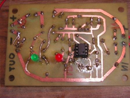
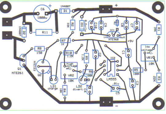
I guess I went about it a little backwards since I spent the time to layout the pcb using "express pcb software", drilled and etched a board, first time for that but it worked out pretty well. I soldered on all of the components and used an 8 pin socket for the 555 chip to make switching out chips easily done, I did make a mistake in the layout program and thats why the 555 is on the back of the board (all pin's are in the correct position though according to the schematic) didn't catch it until the board was already etched.
I incorporated the 9v regulator into my layout, and it works, thats the only change I made and I'm not sure that was even necessary since the 555 can handle up to 18 volts.
All that only to find out it doesn't work, I found out that I had 2 of the pins on the Tip120 or in my case the NTE261 switched, no big deal, cut traces and reroute them to their right locations. That wasn't my problem though with the pins reversed I had voltage present in "dump" and "charge" mode.
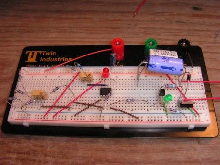
After all of that and trying to find where I might have made another mistake I couldn't find anything so I bought a proto board as I had hoped to try building it on there and making it work. I put more new components on the proto board double checking every connection as per CompDoc's schematic only to find it doesn't work either.
Heres what it does do when I connect power, 1 of the 2 led lights will light up, not always the same one, red or green. Changing the position of either one of the variable resistors does nothing as far as the lights go.
I can however make the opposite led light and it will remain on if I short across C5 or C3. (if red LED or (dump) is lit I can short C3 and the green LED will light and remain lit while red Led goes out, If green LED or (charge) is lit I can short C5 and the red LED will light and remain lit and green LED will go out. All while changing positions of VR1 and VR2 does nothing.
Also changing the input voltage does nothing other than making the Led's get brighter or dimmer until the voltage is so low that the light just goes out.
I do get voltage across the output when the red LED is on and not when the green is on as it should be, the circuit just doesn't control this on it's own.
Not sure this makes a difference since these components should be the same since I cross referenced them to NTE #'s
Tip120 = NTE261
2N3904 = NTE123
7809 = 7805+4v zener or in my case NTE960+4v zener since I couldn't get a 7809
I've checked and rechecked and the only thing left for me to do is ask for help, it may just be something simple but I'm just not seeing it.
Any help in getting this to work would be greatly appreciated so thank you in advance.
methanolcat
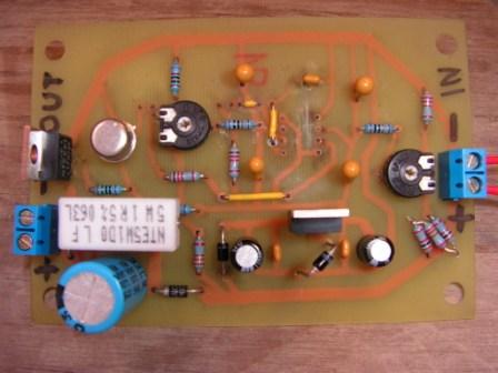
the pin change of the NTE261 can be seen in left side of image near the --
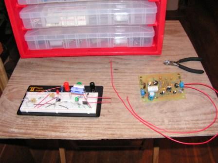
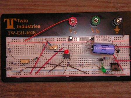
never used one of these boards before but it sure makes changing things easy
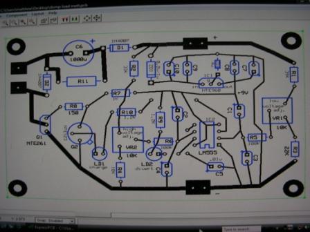
pcb express software, very easy to use and changes made fairly easy, also a free download
print out's of your design are easily done as well
