Author Topic: xantrex pulse frequency  (Read 2681 times)

0 Members and 1 Guest are viewing this topic.

libra

  • Jr. Member
  • **
  • Posts: 81
xantrex pulse frequency
« on: April 01, 2007, 07:31:29 PM »
I have purchased a xantrex c35 and want to reduce its output voltage to about 5-6v to drive another bank of fets, that power my diversion load.


I was told by a dealer that a relay would work but I forgot about the pwm output and the relay chatters like a chipmunk! Ok, and I don't think that a voltage regulator like a 7805 will work but I don't know.


The manual specs don't give a pulse frequency but I guess about 25kc. Does anyone know for sure?


I want to reduce the 28v output control voltage to 5-6v dc to switch the irl540 bank of fets that switch my dump load.


I will only use the c35 as a means of controlling the irl540 fets as their load is over the sugessted rating of the c35.


Yes I could buy a bigger controller but this should work.


Appreciate any help


Libra

« Last Edit: April 01, 2007, 07:31:29 PM by (unknown) »

Flux

  • Super Hero Member Plus
  • *******
  • Posts: 6275
Re: xantrex pulse frequency
« Reply #1 on: April 01, 2007, 01:50:03 PM »
I don't know anything about the pulse frequency but you have almost unlimited drive capability so you can use a low resistance divider to drive your extra mosfets.


A divider of 2 off 22 ohm low inductance power resistors should be good for standard fets. For logic fets then about 4:1 would be a better ratio. You had better include freewheel diodes across your load resistors as the pwm is likely to be fast enough to produce spikes from conventional wire wound resistors.


Seems a strange thing to do but should work.


Flux

« Last Edit: April 01, 2007, 01:50:03 PM by (unknown) »

libra

  • Jr. Member
  • **
  • Posts: 81
Re: xantrex pulse frequency
« Reply #2 on: April 01, 2007, 02:25:18 PM »
Hi  Thanks for the reply. I have a bank of fets that I know work, I hope to program a pic controller eventually but for now this c35 should work.


And do I understand you correctly that a simple voltge divider should work?

Kind of makes sense, and have you another name for these diodes?


Also I am open to better ideas for sure


Libra

« Last Edit: April 01, 2007, 02:25:18 PM by (unknown) »

Flux

  • Super Hero Member Plus
  • *******
  • Posts: 6275
Re: xantrex pulse frequency
« Reply #3 on: April 01, 2007, 02:38:34 PM »
The divider will drive your fets in PWM mode, you would need to do something different to drive them with dc.


If you switch them quickly in PWM you will need a diode across the load to maintain conduction during any inductive spikes. These need to be fast or Schottky diodes.


They normally are blocking except for the duration of spikes, normally called commutating or freewheeling diodes, they are nothing more than fast diodes.


Flux

« Last Edit: April 01, 2007, 02:38:34 PM by (unknown) »

Nando

  • Hero Member
  • *****
  • Posts: 1058
Re: xantrex pulse frequency
« Reply #4 on: April 01, 2007, 02:56:14 PM »
The C35 seems to have around 100 HZ pulsing frequency, about the same fo the C40.


The controller C35 does not have the capability for reduction of output voltage, I believe it has a set of precision resistors to set the charging voltage.


Also when the battery is reaching the full charge causes the controller to pulse with a duty cycle from 100 to 0 % when fully float charge.


If you want to drive the bank of IRl540 ( I tried to find the data sheet of these Fets, but the value you gave is wrong,) when the battery is charged then another scheme is possible.


You have chosen 5 - 6 volts for what ?.

If for the FETS gates then you may use 12 volts which is a much better level to

keep the FETs deeply saturated, even if the FETS are for digital 5 volts control.


Nando

« Last Edit: April 01, 2007, 02:56:14 PM by (unknown) »

SamoaPower

  • Sr. Member
  • ****
  • Posts: 417
Re: xantrex pulse frequency
« Reply #5 on: April 01, 2007, 03:28:33 PM »
I'm glad to see that someone is taking a sensible approach to extending the diversion current capability of a PWM controller.


Others try to parallel multiple controllers which will screw up the battery charge algorithm.


I measured the PWM rate of my C40 which I believe is similar, if not identical (except for current rating) to your C35. It's 180 Hz. Quite low.


This circuit will probably do it, but I haven't tested it.


The resistors are low values to provide a low source impedance for the gate drive. The zener is just for gate protection and may not be needed.

« Last Edit: April 01, 2007, 03:28:33 PM by (unknown) »

Flux

  • Super Hero Member Plus
  • *******
  • Posts: 6275
Re: xantrex pulse frequency
« Reply #6 on: April 02, 2007, 01:20:58 AM »
Yes that should work. With pwm as low as 180 Hz there is probably no need for the diode across the load resistor but I think I would still include it.


Flux

« Last Edit: April 02, 2007, 01:20:58 AM by (unknown) »

libra

  • Jr. Member
  • **
  • Posts: 81
Re: xantrex pulse frequency
« Reply #7 on: April 02, 2007, 07:12:37 AM »
Hi ALL

I appreciate all the help. I chose the 5-6 volt range as that is what the pic will be able to provide, and I am currently trip these fets with an old 9v battery that put out about 7v.

I have had problems trying to switch a opam voltage divider and am learning to program a pic but that will take a while.


The pulse dc is something I have never experienced before and thought it would be better to ask and look dumb rather than do something dumb.


The fact that the irl540 will easily handle the 12v makes it easier is this application. I appreciate the info and the circuit.


It has been frustrating as I have only been able to let my genny run in very light winds when I can manually switch the dump load. I really want to see what this thing is capable of. It is 15' diameter and at 150', and if the flag is moving I see 150w.

Again thanks and will keep the group advised


Libra

« Last Edit: April 02, 2007, 07:12:37 AM by (unknown) »

SamoaPower

  • Sr. Member
  • ****
  • Posts: 417
Re: xantrex pulse frequency
« Reply #8 on: April 02, 2007, 07:57:27 AM »
It would have been nice if you had mentioned your real intent in the first post because the responses would probably be quite different.


If you want to drive the FETs from a Pic microcontroller, you need a buffer/driver stage in between. Trying to drive them directly from the Pic is a mistake, since you have to provide a high current drive pulse to have them switch efficiently. It's not simply a matter of voltage swing.


If you don't have a data sheet on the FET - get one. The absolute gate voltage limit is +/- 20V. The input capacitance is also a major issue to switch them quickly.


I'm not sure why you want to mess around with the Pic when you already have the C35 which should work fine to do the job.

« Last Edit: April 02, 2007, 07:57:27 AM by (unknown) »

Nando

  • Hero Member
  • *****
  • Posts: 1058
Re: xantrex pulse frequency
« Reply #9 on: April 02, 2007, 03:06:27 PM »
The resistors for this MosFets are too "current Heavy" that should changed to a more practical circuit.


33 OHms change to 10 kilohms

Place a 1000 Ohms from C345 to negative rail ( Source of Fets)

100 ohms replace with an NPN transistor,Base to the the C35, Emitter to the Gates of the MosFets, and the Collector to 12 volts, then add a PNP transistor, Base to the C35, Emitter to the Gates of the MosFets and Collector to the Source of the MosFets.


This way you have a power buffer during ON/OFF transitions, and low power when ON after transitions.


Nando

« Last Edit: April 02, 2007, 03:06:27 PM by (unknown) »

Nando

  • Hero Member
  • *****
  • Posts: 1058
Re: xantrex pulse frequency
« Reply #10 on: April 02, 2007, 03:24:35 PM »
Heck, I did not do a good reading and in the initial message the supply was 24 volts and not 12.


Nando

« Last Edit: April 02, 2007, 03:24:35 PM by (unknown) »

libra

  • Jr. Member
  • **
  • Posts: 81
Re: xantrex pulse frequency
« Reply #11 on: April 03, 2007, 06:54:53 AM »
I am getting confused. can you draw this out?  The fets are IRL 540 and I think that some thought they were irf540 , bit  of a difference.


I also would like numbers of the transistor used for switching.

I was heading into the city this morning as my junk box didn't have the power transistors, so if I get a promp reply I can still make the trip


tx

Libra

« Last Edit: April 03, 2007, 06:54:53 AM by (unknown) »

SamoaPower

  • Sr. Member
  • ****
  • Posts: 417
Re: xantrex pulse frequency
« Reply #12 on: April 03, 2007, 09:27:07 AM »
Yes, I did misread your FET type. Unfortunately, the IRL540 isn't the best choice because of it's rather high Rdson of .077 Ohm. Now I see the why of your drive voltage requirement since it's a logic level device and Vgs = +/-10V max.


Do NOT use the complementary emitter follower circuit described by Nando even if you do have 12V available. You'll certainly pop the FETs. It could be used if you have a 6V supply available but I thought you wanted to run it from the 24V battery.


Nando was correct that the resistor divider I suggested will draw a fair amount of current but I don't consider it an issue since you are dumping anyway and they do offer a low source impedance.


For the IRL540 I would change the 33 Ohm resistor to 22 Ohms. Also the zener should be changed to 7-8V.


I suggest you treat the C35 and the Pic as two separate problems. A different solution is best for each.


I assume you would be using a 5V supply for the Pic. In that case, you could use the following circuit and change the supply shown to 5V.
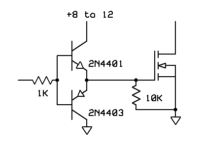


« Last Edit: April 03, 2007, 09:27:07 AM by (unknown) »

libra

  • Jr. Member
  • **
  • Posts: 81
Re: xantrex pulse frequency
« Reply #13 on: April 03, 2007, 09:33:07 AM »
I was wondering about the value of the zener, as to the current draw using the voltage divider, the controller was to dump 35 amps or at least 25 and the divider wouldn't draw more than 5 buy my calculations. This make the controller loaf along.

Sure appreciate the support..


Libra

« Last Edit: April 03, 2007, 09:33:07 AM by (unknown) »

SamoaPower

  • Sr. Member
  • ****
  • Posts: 417
Re: xantrex pulse frequency
« Reply #14 on: April 03, 2007, 04:20:11 PM »
Actually, the divider will load the C35 to about 0.25 Amp at 30V out and maximum PWM duty cycle (100%). Most of the time it will average a lot less. Like you say, the C35 will loaf.

« Last Edit: April 03, 2007, 04:20:11 PM by (unknown) »

libra

  • Jr. Member
  • **
  • Posts: 81
Re: xantrex pulse frequency
« Reply #15 on: April 04, 2007, 10:30:05 AM »
It kinds of works.  I made up a voltge divider last night and got the 5v to the gates on the fets. It did work but the fets sang and the rf was all over the place.

My ham radio, fm radio upstairs and snow on the tv (no cable).


I was using clip leads but don't think it will make any difference, The winds were too high to try powering the batteries with the genny so used the power from a ups.


Might be different with out the dc coming from the ups.


Anyway pretty ticked off. Any good ideas about filters for the control line from the c35. I have pulsed the IRL540 fets rapidly with a battery and there was no hash.


If that don't work I'll have to abandon the pwm controller idea. Xantrex had no idea of how to help.


Frustrated Libra

« Last Edit: April 04, 2007, 10:30:05 AM by (unknown) »

Flux

  • Super Hero Member Plus
  • *******
  • Posts: 6275
Re: xantrex pulse frequency
« Reply #16 on: April 04, 2007, 12:39:37 PM »
Making the thing work as a controller is one thing, reducing rf to levels for ham radio use is a different matter.


Think in terms of a metal enclosure, very careful choice of grounding points, keeping leads as short as practically possible, possibly 22 ohms in series with fet gate and as close to the gate connection as practical. Definitely fit a fast or schottky diode between supply positive and fet drain ( blocking),  probably a rc snubber across the fet all within the earthed metal enclosure. Then you may need an LC filter to the load resistor or keep resistor leads extremely short.


You will need to treat all this as though you were building ham radio equipment, you should be familiar with layouts suitable for medium wave rf.


You may have to degrade the fet switching speed in the extreme case to reduce dv/dt, but not enough to cause serious switching losses.


Flux

« Last Edit: April 04, 2007, 12:39:37 PM by (unknown) »