Author Topic: Homebrew Pure-Sine Inverter  (Read 20455 times)

0 Members and 1 Guest are viewing this topic.

electronrancher

  • Newbie
  • *
  • Posts: 3
Homebrew Pure-Sine Inverter
« on: September 28, 2007, 05:21:47 PM »
Hi All,


I've seen a bunch of UPS and other pure-sine inverter schematics online and passed around between folks, but I don't like the idea of using 60Hz transformers - so heavy and expensive!  Sadly, the Microsine disassembly thread seems to have gotten quiet so I must go fishing elsewhere to compare the tricks of the trade.


Long story short - I bought a little Samlex 300W pure-sine inverter and began tearing it down.  It's direct-drive (no 60Hz transformer) and some of the circuitry is actually pretty clever.  


The circuit sketch is not quite done - they use a very strange gate driver circuit for the 120V output that is partially obscured by potting - but when it is, I will probably post it if anyone is interested.  It's basically a 12v->200v push pull running at 25kHz, a little isolated +/-15v supply for the IC's, and a high-voltage H-bridge PWM at 25kHz to drive the inductor to AC hot.


So are there any other schematics floating around of PSI's that do not use a 60hz transformer?  I'm interested to see any other implementations that may be floating around before I start designing.


I was considering a master/slave mode, where one inverter generates a sine and the others act as grid-tied, following the sine input and driving current only.  But it raises the issues of


  1. Safety - two masters would certainly destroy each other so some sensing must be built-in, complicating the circuit.
  2. Guerilla grid - I'm sure the power company would not want me building devices that could potentially be used for guerilla grid. ;-)

Massive photo removed.
« Last Edit: September 28, 2007, 05:21:47 PM by (unknown) »

boB

  • Sr. Member
  • ****
  • Posts: 389
  • Country: us
    • boB
Re: Homebrew Pure-Sine Inverter
« Reply #1 on: September 28, 2007, 12:04:47 PM »
Yes mr Electron Rancher.  Very nice.  Definately interested in the

schematic you are working on.  I will post another picture I found

of the insides of the OK4U inverter, which looks a bit different

than the one that was posted on that other thread.


Thx,

boB


« Last Edit: September 28, 2007, 12:04:47 PM by (unknown) »

electronrancher

  • Newbie
  • *
  • Posts: 3
Re: Homebrew Pure-Sine Inverter
« Reply #2 on: September 28, 2007, 12:58:20 PM »
Oh, 100k - I get it!  I thought it was a 1000k limit for pictures.  Sorry!


« Last Edit: September 28, 2007, 12:58:20 PM by (unknown) »

juddley

  • Newbie
  • *
  • Posts: 25
Re: Homebrew Pure-Sine Inverter
« Reply #3 on: September 28, 2007, 06:46:09 PM »
I think if you short out R22 and hook up pin 5 of U85 to 12v this board doubles as a launch controller for NASA... Could they have made it any more complicated??  :-)


My only experience in DC-AC design was on the MPU side of a Mororola 68HC7XX family 400hz at 118ac out. We used two A/D converters one to generate the sinewave and one to control the output voltage. It was push pull and used two high volt TDK audio output drivers each capable of driving 60v. WE split the boost supply into both +60 and -60 supplys. One A/D fed the amp in the other fed the "volume" control which was the max PP volts out. There was two inductors one on the boost supply and a choke on the output for smoothing. Total component count of around 30. The part of the design I liked the best was using analog optocouplers as feedback to the mpu to prevent the sinusoidal output wave from "flat topping" and another to detect the "zero crossing point". The other clever thing the analog designer did was to generate all + going pulses then use the inverted output pin of the A/D to drive the negative going half of the sinewave.... during + going half of the wave we blocked the negative amp and vice versa on the - half of the wave. Total wattage was about 30 watts as I recall. Sorry I no longer have the schematics but can draw a block diagram from memory if that helps.


Have built several "heavy iron" inverters (low wattage) over the years as DIY for personal use. Just old 60hz transfers and oscillators. But what is interesting now is the number of devices using switching type supplys is increasing dramatically and they don't care if the input is AC or DC, Square or Sinusoidal wave. Someday the whole world will be run by a giant wall wart.


When you say "....master/slave mode..." do you mean sine wave syncronizing?? I can't visualise driving just the current.... wouldn't it have to do both V and A?


Juddley

« Last Edit: September 28, 2007, 06:46:09 PM by (unknown) »

electronrancher

  • Newbie
  • *
  • Posts: 3
Re: Homebrew Pure-Sine Inverter
« Reply #4 on: October 01, 2007, 11:26:09 AM »
Ha ha!  You're right that it's complicated - sadly, using 100 resistors and capacitors at 1/10th of 1 cent is still cheaper than a 12 cent IC so a lot of these low-end devices are heavy on the discrete components.  Thanks for the ideas on the MPU-controlled output stage.  I'd love to see a block diagram if you don't mind drawing something up!


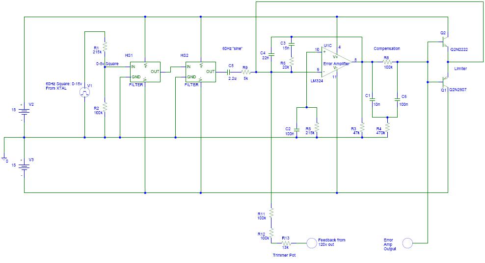
On to the samlex circuit.  It's always interesting to see how people make their sine wave - most popular these days is storing the digitized wave in ROM and churning it out to a DAC.   But these guys used a couple of op-amp low-pass filters to filter down a 60hz clock (from a 30.7kHz crystal, and binary counter) to a pseudo-sine.  It's not perfect, but it seems to work pretty well.


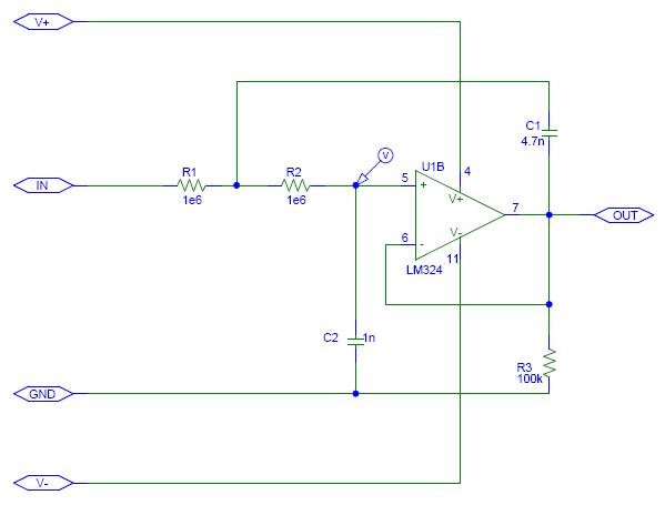
So here's the filter.  They use two (basically) identical stages for shaping. First one gets a 0-5v square wave and shapes it a bit, then passes to a second stage for a little fine-tuning.  


Next, they pass it through a 2.2uF cap and on to the error amp to compare the reference sine with a divided down portion of the output from AC hot.  Any small difference between reference sine and output is amplified, and this error signal that I call "COMP" (short for COMPENSATION) is passed to the PWM circuit.  The error signal is limited by a couple of bjt transistors - if it gets too big, these bjt's overdrive the input to bring it back.  Kind of a crude limiter to keep the output stage from driving itself to death in a short circuit.


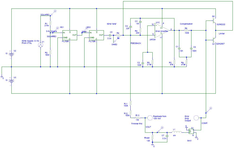
The PWM comparator can be modelled as a current source, which is what I've done in this next schematic to close the loop.  The output of COMP tells the PWM stage how much current to give the output, and the 110k/100k/13k resistor divider provides feedback to the error amp.  Never saw this kind of error amp and compensation network before, but these guys are old school so who knows what topology they learned back in the stone age.  Hehe!


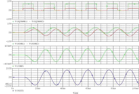
And finally, here's the PSPICE simulation of the whole loop.  I start with a 60Hz square wave which is filtered down to pseudo-sine and fed to the error amp.  Then my fake output stage gives whatever current (up to 5A) is requested by the error amp.  Lo and behold - the loop works when closed!  You can see the two stages of filtering and the final output of 169v (120v RMS).  As long as the output stage can give the requested current, this little guy will faithfully track the reference.  


Crude, but effective.  


« Last Edit: October 01, 2007, 11:26:09 AM by (unknown) »

(unknown)

  • Guest
Re: Homebrew Pure-Sine Inverter
« Reply #5 on: November 24, 2007, 04:29:54 PM »
Good stuff! I am trying to do the same thing. I used a fancy XR2206 waveform generator to produce a nice sine wave. I have a 300VA 240V to 9V toroidal from Altronics to do the step up but am intending on looking at a switchmode design for a second UPS. (I have been given 2 old 24AH gel cells). I got it working ok but using a centre tapped arrangement and various modulation techniques, the best being last weekend with 2 TL494s running in sync. I am doing unipolar switching as I have found this works a lot better than bipolar for a centre tapped system. This weekend I borrowed my flatmate's pic board & programmed it to alter it's pwm modules with a 16 sample sine. This works gr8 and I have an adc giving feedback to scale the amplitude of the sine. I however have only got an opamp driving 4 paralleled FETs and they get fairly hot at a 60W lamp load.


I am really in a dilemma as to what to try next. The output is a bit (lot) on the low side and regulation is poor. Considering going for modified sine which works very easily, just a 555 and a decade counter but I always wanted my design to be a proper sine unlike cheapo off the shelf ups's. I also don't want to blow up these fets as I ordered them from farnell at quite an expense. This project has been going for a year & I have a new computer and so will be needing more like 350W+ when gaming to run 2 gaming machines. However, the 300W ups would work well in my shed where I have an old pentium 3.


Thanks for sharing your circuits, when I get a design I am happy with I'll publish it on my website.


Regards,


Rory

« Last Edit: November 24, 2007, 04:29:54 PM by (unknown) »

(unknown)

  • Guest
Re: Homebrew Pure-Sine Inverter
« Reply #6 on: April 01, 2009, 01:11:31 PM »
I traced out the schematics for an old Statpower Prosine inverter. Would that help?
« Last Edit: April 01, 2009, 01:11:31 PM by (unknown) »

caravelle

  • Newbie
  • *
  • Posts: 1
Re: Homebrew Pure-Sine Inverter
« Reply #7 on: December 06, 2011, 02:10:15 PM »
Hi, I would like to get a copy of the schematic for the old Statpower Prosine inverter. Thank you,Ken