Author Topic: convert 12 v charger to 24 v  (Read 2985 times)

0 Members and 1 Guest are viewing this topic.

youmanskids

  • Jr. Member
  • **
  • Posts: 68
convert 12 v charger to 24 v
« on: January 06, 2010, 07:29:41 PM »
I bought a 12 volt Diehard charger/starter,  2A/40A/200A model.  Id like to rewire it to put out a 24 v charge so I could carge my bank all at once without having to reconfigure it every time as some others have had to do.  has anyone done this with this particular charger?  It has multiple primary taps, one is for 2A, one for 40A and one for the 200A settings which switch from one leg of the 110 ac line,  the other leg of the 110 ac goes to one of two leads (one unused).  the secondary has 2 outputs, each one goes to 2 diods on the rectifier assembly.  I cant find a schematic for this charger (transformer) and have searched the site for with no results.  If there is a simple way to reconfigure the transformer and someone has done this successfully I sure would appreciate the help.  thanks in advance, Roger Y.
« Last Edit: January 06, 2010, 07:29:41 PM by (unknown) »
Praise be to God of the universe, who gives us WIND for power.

youmanskids

  • Jr. Member
  • **
  • Posts: 68
Re: convert 12 v charger to 24 v
« Reply #1 on: January 06, 2010, 07:44:02 PM »
by the way,  this is a manual charger.  thanks
« Last Edit: January 06, 2010, 07:44:02 PM by (unknown) »
Praise be to God of the universe, who gives us WIND for power.

Opera House

  • Sr. Member
  • ****
  • Posts: 261
Re: convert 12 v charger to 24 v
« Reply #2 on: January 07, 2010, 03:52:17 AM »
'the secondary has 2 outputs, each one goes to 2 diods on the rectifier assembly.'


So is that 4 diodes total?   If it is then you could add two capacitors and make it a voltage doubler.  Practical limit would be about 10A. That would be on the 5A position since the capacitors create higher voltage than unfiltered DC.  

« Last Edit: January 07, 2010, 03:52:17 AM by (unknown) »

TomW

  • Super Hero Member Plus
  • *******
  • Posts: 5130
  • Country: us
Re: convert 12 v charger to 24 v
« Reply #3 on: January 07, 2010, 05:06:09 AM »
Opera House;


That is downright sneaky.


Thanks.


Tom

« Last Edit: January 07, 2010, 05:06:09 AM by (unknown) »

TomW

  • Super Hero Member Plus
  • *******
  • Posts: 5130
  • Country: us
Re: convert 12 v charger to 24 v
« Reply #4 on: January 07, 2010, 05:13:30 AM »
And this page explains a voltage multiplier with a schematic at the bottom.


http://www.tpub.com/neets/book7/27m.htm


Or the nutshell version if you understand schematics:


Tom

« Last Edit: January 07, 2010, 05:13:30 AM by (unknown) »

ghurd

  • Moderator
  • Super Hero Member Plus
  • *****
  • Posts: 8059
Re: convert 12 v charger to 24 v
« Reply #5 on: January 07, 2010, 05:54:03 AM »
Why net get a 24V charger?

I got one cheap that was billed as surplus for army trucks.

G-
« Last Edit: January 07, 2010, 05:54:03 AM by (unknown) »
www.ghurd.info<<<-----Information on my Controller

Opera House

  • Sr. Member
  • ****
  • Posts: 261
Re: convert 12 v charger to 24 v
« Reply #6 on: January 07, 2010, 07:25:45 AM »
I would prefer the circuit of 4-49 in that article.   That way the existing diodes could be used in the charger and the capacitors could stay in place.   A switch could then select between connecting the other transformer secondary wire to the other diodes for 12V or the center of the two capacitors for 24V.  
« Last Edit: January 07, 2010, 07:25:45 AM by (unknown) »

youmanskids

  • Jr. Member
  • **
  • Posts: 68
Re: convert 12 v charger to 24 v
« Reply #7 on: January 07, 2010, 11:06:04 AM »
thanks opera house,  that looks simple enough to build, but what values for the resistors, capacitors and diodes (and type) whould be appropriate for the 24v/10A output? if you could give suggestions on these, I'll get to radio shack and see what they have- and build it.  Thank you very much for your help! Roger.
« Last Edit: January 07, 2010, 11:06:04 AM by (unknown) »
Praise be to God of the universe, who gives us WIND for power.

Norm

  • Hero Member
  • *****
  • Posts: 1841
  • Country: us
  • Ohio's sharpest corner
Re: convert 12 v charger to 24 v
« Reply #8 on: January 07, 2010, 12:45:45 PM »
The simplest way I can think of ....Just get

another charger ! Then I think you can just hook

them in series or charge half the 24 bank with each one.


Now if you had waited till they were on sale...

you could have got them for not much more than

you paid for one....

C'mon....it's only money !  LOL !

« Last Edit: January 07, 2010, 12:45:45 PM by (unknown) »

Ungrounded Lightning Rod

  • SuperHero Member
  • ******
  • Posts: 2865
Re: convert 12 v charger to 24 v
« Reply #9 on: January 07, 2010, 01:39:26 PM »
You can leave the diodes in place.  Just a single-pole switch between the junction of the caps and crowbar discharge resistors on one side and the junction of one end of the transformer winding and its diodes on the other:

 - Closed = doubling.  (The "unused" diodes protect the capacitors from reverse voltage if they're over-discharged by a heavy and/or inductive load.)

 - Open = normal.  (The capacitors add a bit of extra filtering and the crowbar resistors keep the voltage equally split between them if they have unbalanced leakage.  Average voltage may be slightly higher than before the capacitors were added.)


Note that your diodes need a higher peak-inverse-voltage rating in the doubling mode.  Be sure the ones supplied are up to it.

« Last Edit: January 07, 2010, 01:39:26 PM by (unknown) »

youmanskids

  • Jr. Member
  • **
  • Posts: 68
Re: convert 12 v charger to 24 v
« Reply #10 on: January 07, 2010, 07:04:14 PM »
ya,  it does seem like the more you spend the funner it gets!! lol.  but i'm in it for the challenge, but lighning rod is still over my head.  my transformer doesnt have any caps that I can see,  the output of the 2ndry goes right to diodes and then to output.  i though i could build a doubler curcuit to add to the output side of the trasformer- seperate from the existing 4 diode plate..? not sure what he means--

 unerground lighning rod,  could you try to educate me a bit more, the curcuit you reference looks easy to build if i knew the values of the components, and seems to me (moderately ignorant) that it would tack on the output of the transformer?  help.  thanks, Roger.
« Last Edit: January 07, 2010, 07:04:14 PM by (unknown) »
Praise be to God of the universe, who gives us WIND for power.

youmanskids

  • Jr. Member
  • **
  • Posts: 68
Re: convert 12 v charger to 24 v
« Reply #11 on: January 07, 2010, 07:06:28 PM »
see below, thanks (sorry, i just noted that it is "ungrounded" lightning rod (my wife would say 'slow down and read your words')
« Last Edit: January 07, 2010, 07:06:28 PM by (unknown) »
Praise be to God of the universe, who gives us WIND for power.

youmanskids

  • Jr. Member
  • **
  • Posts: 68
Re: convert 12 v charger to 24 v
« Reply #12 on: January 08, 2010, 07:28:56 AM »
hey Tom, could you suggest values for diodes, R1,R2, RL, and caps to build the doubler you referenced? thanks. (lots of various input from the board, a bit confusing) thanks for all you guys help.  Roger
« Last Edit: January 08, 2010, 07:28:56 AM by (unknown) »
Praise be to God of the universe, who gives us WIND for power.

Opera House

  • Sr. Member
  • ****
  • Posts: 261
Re: convert 12 v charger to 24 v
« Reply #13 on: January 08, 2010, 01:06:44 PM »
I would want to use at least 10,000uF capacitors of 20V or higher.  These would have to be what they used to call "computer grade" types with screw terminals on the top and 3 or more inches in diameter.  Preferably using two or more caps in parallel.  Something off the rack at Radio Shack will blow up from overheating.  A 300 to 2,000 ohm resistor is just used on each capacitor to balance the voltage and is not necessary if capacitors are 35V or more.  I would upload a schematic If that feature worked for me.  Any ideas why it appears on my upload list and not in the insertion list.   If you were to do this I would make this an external circuit and mod the charger with an extra terminal for the transformer connection.  I doubt you have enough space in the charger.  

« Last Edit: January 08, 2010, 01:06:44 PM by (unknown) »

youmanskids

  • Jr. Member
  • **
  • Posts: 68
Re: convert 12 v charger to 24 v
« Reply #14 on: January 08, 2010, 02:23:48 PM »
thats what i needed,  thanks. i went to your files and your "doubler" scematic makes sense.  I just need the caps, ballancing resistors and a switch.   I'll give it a try and see if it blows up!! thanks again everyone.  Roger.
« Last Edit: January 08, 2010, 02:23:48 PM by (unknown) »
Praise be to God of the universe, who gives us WIND for power.

Ungrounded Lightning Rod

  • SuperHero Member
  • ******
  • Posts: 2865
Re: convert 12 v charger to 24 v
« Reply #15 on: January 08, 2010, 04:16:14 PM »
I'll give it another shot.


Opera House pointed to "circuit of 4-49 in that article."  Here's the circuit:
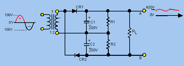


Now imagine a "CR3" and "CR4" from the OTHER end of the transformer to A and B respectively.  What you'll have is your charger with transformer and bridge rectifier, with the capacitors and resistors added.


With the capacitors and resistors in place the other two original rectifier diodes hang across the capacitors backwards.  In normal circumstances they're always reverse biased and never conduct.  But there's a bonus:  In case of some trouble that tries to reverse-charge the capacitors these "unused" diodes will act as reverse-voltage clamps, limiting the reverse voltage across the capacitors to the forward voltage drop of the diodes, about 0.6V.  This should be low enough to protect electrolytic capacitors from destruction by the reverse voltage.


So if you add the capacitors (and resistors) to your existing charger you turn it into a voltage doubling charger.  Let's go a little farther:  Put a switch in to disconnect (any two of) the three connections where you add the capacitors and resistors.  Switch off, no doubling.  Charger is as it was.  Switch on, it's a doubler.


But why use a two-pole?  Just disconnect the MIDDLE connection and leave the top and bottom ones connected.  Switch on, doubler.  Switch off, original charger with a series pair of capacitors across the output.  (Plus the resistors:  R1 and R2 act as "leakage balancing" and "discharge crowbaring" resistors.  They keep the two capacitors splitting the voltage evenly during operation even if the leakage in the capacitors is unbalanced and gradually discharge the capacitors when the power is turned off.  RL is just a load to keep the cap voltage from climbing unreasonably if there's little output load.  With the capacitors the output voltage would tend to hang at the peak of the cycle rather than visit there momentarily as it does with just the rectifier.)


Resistor values:  I'd pick this:


R1 and R2:  About 12K.  This pulls a thousandth of an amp.  That should be large compared to the leakage of the caps and will discharge them eventually when the power is off, but will only eat about a fortieth of a watt when things are running.  If you're going to leave the charger hooked to the batteries with the power off, leave 'em out and be sure your caps are rated 30 volts or more.  Then they won't need balancing.


RL:  Why bother?  Leave it out.

« Last Edit: January 08, 2010, 04:16:14 PM by (unknown) »

Ungrounded Lightning Rod

  • SuperHero Member
  • ******
  • Posts: 2865
Re: convert 12 v charger to 24 v
« Reply #16 on: January 08, 2010, 04:22:00 PM »
I see that Opera House has suggested either 35V caps (with no R1/R2) or lower value balancing resistors.  I'd go with his numbers rather than mine.
« Last Edit: January 08, 2010, 04:22:00 PM by (unknown) »

youmanskids

  • Jr. Member
  • **
  • Posts: 68
Re: convert 12 v charger to 24 v
« Reply #17 on: January 31, 2010, 08:09:59 PM »
well I got the 1300 uF caps and when I went back to the carger's transformer, it didnt match the single 12v ac output I thought it had.  The 2ndry winding has 4 outputs on the positive side, all tied to a common bus via 4 large diodes-(a bridge recifier set up I assume)- this goes to the positve output cable,  the negative side has 2 output wires going straight thru the ammeter and to the neg output cable- no recifiing diodes.  sooo,  not sure where to tie in the doubling cicuit.  I tried one of the 4 output wires and sure enough it doubled the voltage but only put out minimal current ( 0.1 amp)  that aint gonna work... so to speak.  I realy need an internal schematic of the transformer windings and termials (5 input and 6 output termials) to know how to do this.  ALL termianls test positive for continuity... all of them are test common with all other output conections.. how is that possible?  without a schematic for reference Im still lost.

  The doubler circuit did indeed work but I'm just not able to appy it to this paritcular transformer without more info.

   I ended up getting an old military surplus power supply for $89 plus shipping, It puts out 2-32v and 0-15amps for bulk charging my 24v bank- I just have to keep manually adjusting the voltage up to keep up the amps until it gets up to 28.5v (full while bulk charging). not what I originally wanted but it works.

  Thanks to all of you who helped me with advice, I really appreciate it. this is a great board.  thaks again,  Roger.

« Last Edit: January 31, 2010, 08:09:59 PM by (unknown) »
Praise be to God of the universe, who gives us WIND for power.