Author Topic: Bicycle Generator Project  (Read 30393 times)

0 Members and 1 Guest are viewing this topic.

jaysicle

  • Jr. Member
  • **
  • Posts: 73
Re: Bicycle Generator Project
« Reply #33 on: May 18, 2011, 06:58:22 PM »
Good pictures, nice write up, great pedgen.

Suppose I should brace for sudden resistance drop when it kicks in :)

I have a ghurd controller on this setup, and it does a gradual turn on, nothing sudden.

Enjoyed checking that post out zap. Particularily your fan RPM control with temperature rise. Nice.

Also cool that it won't feel like my chain broke when controller kicks in.
Wasn't completely expecting that it would, but just in case...

 
« Last Edit: May 18, 2011, 08:02:16 PM by jaysicle »
Marble cake is hard on the teeth.

jaysicle

  • Jr. Member
  • **
  • Posts: 73
Re: Bicycle Generator Project
« Reply #34 on: May 18, 2011, 07:44:19 PM »

Suppose I should brace for sudden resistance drop when it kicks in :)


No shock with a decent size battery.  It takes power from the battery to hold it at a stable voltage, and you are pedaling into the battery at a stable voltage.
So no shock.

Shock comes from some of the goofy controller designs, which IMHO are not good for a pedal or wind generator... or anything else.
G-

Riding with the power resistor for testing offered some physical resistance, I would guess at 0.125 opposing force 'feel' of battery connection.
When the controller kicks 'off' should I expect a gradual ramp in physical resistance that way as well?

BTW - I am slow in installing the controller. Had to modify a 200mV LCD panel meter I picked up for it to read 20V max, and move decimal and such. The schematics were vague, but I sorted it out. I want it to work right along with controller and have a clear visual (aside from my DMM). I have nothing against DMMs and aligator clips for testing, but seeing all of the wires hanging about gives others something to worry about. Will take some time with proper layout and mount as well. Likely during the weekend though...
« Last Edit: May 18, 2011, 07:49:21 PM by jaysicle »
Marble cake is hard on the teeth.

Norm

  • Hero Member
  • *****
  • Posts: 1841
  • Country: us
  • Ohio's sharpest corner
Re: Bicycle Generator Project
« Reply #35 on: May 18, 2011, 08:11:35 PM »
Good pictures, nice write up, great pedgen.

Suppose I should brace for sudden resistance drop when it kicks in :)

I have a ghurd controller on this setup,


from this post and it does a gradual turn on, nothing sudden.
  On (this post)

Yep and I asked you what ratio or speed you had the bike in when friction driving the
flywheel of the treadmill motor and you said you'd get back to me....must have missed that?
LOL
Norm.

Bruce S

  • Administrator
  • Super Hero Member Plus
  • *****
  • Posts: 5374
  • Country: us
  • USA
Re: Bicycle Generator Project
« Reply #36 on: May 20, 2011, 02:16:38 PM »
OP :My Apologies for the slight drift.
NORM,
Finally have some time to sort out some of your pics :)
Tell IF I'm wrong but that looks like one of your new style batt-packs and should come in at 12Vdc ~12Ahr?
VERY NICE
Bruce S
A kind word often goes unsaid BUT never goes unheard

jaysicle

  • Jr. Member
  • **
  • Posts: 73
Re: Bicycle Generator Project
« Reply #37 on: May 24, 2011, 11:58:48 AM »
OP :My Apologies for the slight drift.
Bruce S

No problem.  ;)

------------------------------------

Update on ghurd controller build / implementation -
IT WORKS!, IT WORKS!...

I am very pleased and excited to offer the following shots of the working ghurd controller now built into my system !

Seriously, I was giddy watching this trigger and dump while riding the bike, adjusting the voltage limit, trying it again, etc..
It tracked, dumped power and clamped the voltage perfectly.

Will enter some more build details later today / this evening. 1st photo shows front panel meter calibration (to my DMM anyway  :P)
during test runs.  2nd photo shows more of a top view with controller in lower right.

3127-0

3128-1
« Last Edit: May 24, 2011, 12:12:36 PM by jaysicle »
Marble cake is hard on the teeth.

jaysicle

  • Jr. Member
  • **
  • Posts: 73
Re: Bicycle Generator Project
« Reply #38 on: May 24, 2011, 04:30:44 PM »
Quote
No shock with a decent size battery.  It takes power from the battery to hold it at a stable voltage, and you are pedaling into the battery at a stable voltage.
So no shock.

Shock comes from some of the goofy controller designs, which IMHO are not good for a pedal or wind generator... or anything else.
G-

Confirmed. Empirical data / experience with the controller operation in my particular set-up today. When the controller kicks in and out, as ghurd described - it does not do anything severe to physical resistance at pedals. The controller just trims what is needed, and goes about its business that way. In fact, I were to choose a way to describe the operation/effect of the controller in this set-up in a physical regard it would be 'Smooth'. Describing it in an electrical/electronic regard, it would be - 'Bloody Accurate'.

Today was a good system test as well, since overall it saw a full sun charge with solar panels and what ended up being a regular workout - (was there anyway)... on the bike generator at same time.  

Good times.
« Last Edit: May 24, 2011, 05:04:10 PM by jaysicle »
Marble cake is hard on the teeth.

ghurd

  • Super Hero Member Plus
  • *******
  • Posts: 8059
Re: Bicycle Generator Project
« Reply #39 on: May 24, 2011, 05:38:34 PM »

IT WORKS!, IT WORKS!...


Did you have any doubts?    8)

Giddy is why the concept is so addictive.
People who never saw the yellow LED flickering can not understand it.

Quote

Today was a good system test as well, since the system saw full sun charge with solar panels and what ended up being a regular workout - (was there anyway)... on the bike generator at same time.   


More than one way to skin a cat.
Myself, being lazy, I would rig the solar to power the ped-gen.
Then the required time of the exercise bike operation could be met automatically with solar power, while I nap, or watch TV on the sofa eating potato chips!
 ::)
G-
www.ghurd.info<<<-----Information on my Controller

Madscientist267

  • Hero Member
  • *****
  • Posts: 1181
  • Country: us
  • Uh oh. Now what have I done?
Re: Bicycle Generator Project
« Reply #40 on: May 24, 2011, 06:48:57 PM »
I'm with you there... LOL

If exercise involves more than tippety tap and left click right click, with the occasional grab for a screwdriver and soldering iron, let the panels do it.

All jokes aside, I probably SHOULD build something like this... I am only getting older. And with that comes more and more out of shape.

Besides, pedal power is there, rain or shine, night or day, wind or no wind... ;)

Steve
 
The size of the project matters not.
How much magic smoke it contains does !

Norm

  • Hero Member
  • *****
  • Posts: 1841
  • Country: us
  • Ohio's sharpest corner
Re: Bicycle Generator Project
« Reply #41 on: May 24, 2011, 07:38:21 PM »


All jokes aside, I probably SHOULD build something like this... I am only getting older. And with that comes more and more out of shape.

Besides, pedal power is there, rain or shine, night or day, wind or no wind... ;)

Steve
 
Careful !  ....pedal generating is Very addictive !  LOL !
Norm.

jaysicle

  • Jr. Member
  • **
  • Posts: 73
Re: Bicycle Generator Project
« Reply #42 on: May 24, 2011, 09:18:16 PM »

IT WORKS!, IT WORKS!...


Did you have any doubts?    8)

Giddy is why the concept is so addictive.
People who never saw the yellow LED flickering can not understand it.

Quote

Today was a good system test as well, since the system saw full sun charge with solar panels and what ended up being a regular workout - (was there anyway)... on the bike generator at same time.  


More than one way to skin a cat.
Myself, being lazy, I would rig the solar to power the ped-gen.
Then the required time of the exercise bike operation could be met automatically with solar power, while I nap, or watch TV on the sofa eating potato chips!
 ::)
G-


Sour Cream and Onion... mmmm. I didn't actually have doubts about the ghurd controller, or design - just sometimes overall these things don't work out so nicely...

Here are shots of the build...  I'd had an aluminum/steel case in my closet for a while now...  

3131-0


So I used that and started mounting parts inside it based on an unproven layout in my head....
Maybe one day I will build an isolated supply or floating ground for the meter so I won't have to use a 9V battery.


3132-1

Then laid out and cut the through hole for the battery panel meter, and wired the 9V holder to it, sending Battery sense wires off to the right as well.

3133-2

3134-3

3135-4
 
« Last Edit: May 24, 2011, 09:35:28 PM by jaysicle »
Marble cake is hard on the teeth.

jaysicle

  • Jr. Member
  • **
  • Posts: 73
Re: Bicycle Generator Project
« Reply #43 on: May 24, 2011, 09:32:04 PM »
Cut holes and mounted illuminated rockers for panel meter and ghurd dump control power and dump LED...  
( I used the green LED for dump, since green lends a more positive reaction to both myself and outsiders.)
I hope that the controller warranty is not void due to this. 

3136-0

Then I mounted the ghurd controller on a stand off (1/8" bolt assy) through the bottom of the case, and wired in a terminal block for the fets / possible expansion. Should note here that sub assembly of the ghurd controller was done about a week ago, and posted earlier. The board is small and robust, and traces and components are laid out so that it is really tough to solder incorrectly.  

3137-1
  
« Last Edit: May 24, 2011, 11:01:07 PM by jaysicle »
Marble cake is hard on the teeth.

jaysicle

  • Jr. Member
  • **
  • Posts: 73
Re: Bicycle Generator Project
« Reply #44 on: May 24, 2011, 09:51:20 PM »
I didn't have a way to mount the fets properly. The kit came with heat sinks (and even the thermal transfer paste already applied), so I figured that I'd better get this right.

I used/sacrificed an old acrylic photo stand. Cut with a 0.7mm Olfa knife, heated close to melt and formed (5) of these 'L' brackets...  


3138-0

Here they are mounted and waiting for wiring....

3140-1
« Last Edit: May 24, 2011, 10:01:04 PM by jaysicle »
Marble cake is hard on the teeth.

jaysicle

  • Jr. Member
  • **
  • Posts: 73
Re: Bicycle Generator Project
« Reply #45 on: May 24, 2011, 10:13:16 PM »
Next came the fet mounting. Had Aluminum angle, used that and screwed that in to keep the 'L' brackets snug. There is about a 1/2" gap between aluminum angle and fet mount bolt end.

Wired all of the gates.

3141-0

Needed a safe way to get battery connection to case, so cut clear hole through case, and used piece of black heavy plastic sign material to isolate posts and fastened that to the case.

3142-1

Drilled and tapped for power resistors and mounted those, with some air gap between them, and all fets and power resistors toward rear of housing to utilize case lid vents. (Case lid with vents not shown)

3143-2
 

Wired drains to resistors...


3144-3


« Last Edit: May 24, 2011, 11:15:53 PM by jaysicle »
Marble cake is hard on the teeth.

jaysicle

  • Jr. Member
  • **
  • Posts: 73
Re: Bicycle Generator Project
« Reply #46 on: May 24, 2011, 10:41:28 PM »
Wired in a fuse block between the battery in and fet drain / source. And wired 10AWG RED and BLK to those.

3145-0


Finallly, aside from initial photos of the more of less complete controller - a side view. (I'll post another few photos of the installation into battery bank table) - Will likely need to illuminate the panel mount meter because of battery shelf. I suppose a backlit LCD / LED type can be had from ebay to alleviate this, but it is what I had - and that will be fun to do as well I think... Shown here (but a little hard to pick up) - are the diodes in parallel with each power resistor. I will likely clean this part of wiring up a bit with heat shrink tubing etc., but it has passed initial trial(s).

3146-1

The controller in operation really is pretty cool to watch. I would ride for a while, see it trigger (LED flicker and hold ghurd mentions above) - Dump - keep riding into dump loads - then get off the bike and check to see if the resistors are warm. - They are!... do it again at various settings - for close to an hour. Best Tuesday I have had in a while. True, I should get out more - but overall... Good times.

I also like that I won't need to use the DMM and wires on the battery table (as often).

I don't see a short term requirement for fan assist, with the amount that I am dumping - but will consider this if the system expands. Did I just say if ?     :)


« Last Edit: May 24, 2011, 11:33:29 PM by jaysicle »
Marble cake is hard on the teeth.

jaysicle

  • Jr. Member
  • **
  • Posts: 73
Re: Bicycle Generator Project
« Reply #47 on: May 24, 2011, 11:43:10 PM »
I'm with you there... LOL

If exercise involves more than tippety tap and left click right click, with the occasional grab for a screwdriver and soldering iron, let the panels do it.

All jokes aside, I probably SHOULD build something like this... I am only getting older. And with that comes more and more out of shape.

Besides, pedal power is there, rain or shine, night or day, wind or no wind... ;)

Steve


Steve, if you do decide to build one - I have ran this one for a bit now... and have noticed a distinct advantage in tilting the bike on a slight downward slope. It is almost always easier to ride downhill.   :P
« Last Edit: May 24, 2011, 11:47:57 PM by jaysicle »
Marble cake is hard on the teeth.

SparWeb

  • Global Moderator
  • Super Hero Member Plus
  • *****
  • Posts: 5452
  • Country: ca
    • Wind Turbine Project Field Notes
Re: Bicycle Generator Project
« Reply #48 on: May 26, 2011, 12:05:31 AM »
Ghurd,
Have you suggested, to others, in the past, that multiple FETs should better have their own separate resistors on the gate?
I was going to suggest it for Jay but I've gotta defer to the expert first.
No one believes the theory except the one who developed it. Everyone believes the experiment except the one who ran it.
System spec: 135w BP multicrystalline panels, Xantrex C40, DIY 10ft (3m) diameter wind turbine, Tri-Star TS60, 800AH x 24V AGM Battery, Xantrex SW4024
www.sparweb.ca

jaysicle

  • Jr. Member
  • **
  • Posts: 73
Re: Bicycle Generator Project
« Reply #49 on: May 26, 2011, 01:32:33 AM »
Ghurd,
Have you suggested, to others, in the past, that multiple FETs should better have their own separate resistors on the gate?
I was going to suggest it for Jay but I've gotta defer to the expert first.


Balancing resistors on each gate...?  - I am all ears.  :)

Guys, separate (minor) issue to report...  I bought (5) 2.5ohm power resistors (dump side) for this project...  and just realized that the second power resistor from left is actually 1.7ohm - it was a little warmer than the rest of them while testing during todays ride, which drew my attention / made me focus on the body labeling. The ink is smudged a bit on that one... making out 1.67 at 3% is the best guess I have (combined with my DMM telling me it is 1.7ohm when all of the others measure closer to their 2.5ohm screening) - -  I think I should get that corrected.

These things might give me an opportunity to clean up wiring a bit as well.  
« Last Edit: May 26, 2011, 01:47:11 AM by jaysicle »
Marble cake is hard on the teeth.

ghurd

  • Super Hero Member Plus
  • *******
  • Posts: 8059
Re: Bicycle Generator Project
« Reply #50 on: May 26, 2011, 01:35:05 AM »
Ghurd,
Have you suggested, to others, in the past, that multiple FETs should better have their own separate resistors on the gate?
I was going to suggest it for Jay but I've gotta defer to the expert first.


In another context, yes.
The problem occurs when the fets are paralleled, then connected to paralleled resistors (or one giant load), resulting in ONE big sub assembly made of 5 fets and 5 resistors.

This system has individual loads, each with their own individual fet, and each fet has its own electrically isolated heat sink (the reason for 5 pieces of "old acrylic photo stand").
The result is FIVE completely separate sub assemblies, each with 1 fet and 1 resistor.

If Jaysicle would have screwed the fets to the heat sink looking thing behind them (sort of looks like they are, but they are not),
then I expect the fets would eventually experience a cascading failure scenario (meaning 5 separate booms as the fets popped).

Good call either way,
G-
www.ghurd.info<<<-----Information on my Controller

ghurd

  • Super Hero Member Plus
  • *******
  • Posts: 8059
Re: Bicycle Generator Project
« Reply #51 on: May 26, 2011, 02:10:56 AM »

 just realized that the second power resistor from left is actually 1.7ohm - it was a little warmer than the rest of them while testing during todays ride, which drew my attention / made me focus on the body labeling. The ink is smudged a bit on that one... making out 1.67 at 3% is the best guess I have (combined with my DMM telling me it is 1.7ohm when all of the others measure closer to their 2.5ohm screening) - -  I think I should get that corrected.

These things might give me an opportunity to clean up wiring a bit as well.  

Is there some heat sink compound between the resistors and the metal where they are mounted?
How thick is that metal?
What watts are the resistors rated to handle?
And how hot is the 1.7 ohm resistor?

That type of resistor is typically required to be mounted on a heat sink to operate continuosly at the rated watts, so heat sink compound and thicker metal is best.
If you can leave your finger on the resistor after a long time of dumping, then it is fine as it is.


The duty cycle is pretty low too, so the resistors get a chance to cool down during the 'off' part of the cycle.
Duty cycle of the resistors comes into play here.  The battery takes a quantity of amps (watts) to maintain dump voltage.  The other 4 resistors are dumping over 300W(?).  The 1.67 ohm resistor is dumping over 100W.
Combined, that means the operator must maintain well over 400W to keep the resistors operating at 100% duty cycle.
If the operator can manage over 100W into the battery for a long time after they battery makes it to dumping voltage, then the resistors are operating at below 25% duty cycle.

Most people stop pedalling after the Yellow LED flickers a few times, so the resistors never get a chance to get too hot.
G-
www.ghurd.info<<<-----Information on my Controller

jaysicle

  • Jr. Member
  • **
  • Posts: 73
Re: Bicycle Generator Project
« Reply #52 on: May 26, 2011, 02:11:45 PM »
Currently no heat sink compound under resistors, but just picked some more up - so there will be.
Case thickness = 0.05" , material = lightly painted steel (I see lightly sanding that in my future).
Resistors are rated at 50W, so 250W total. Current solar panel contributes '54W', - I have seen 32W.

I have a 2" strip of 0.10" thick aluminum that I can use to sink these some more, and apply the paste - maybe I'll look for some aluminum heat sink to clamp to them, and I did pick up a replacement 2.49ohm 50W resistor to match the others.

There is room for another three FETs and resistors, may just order those and build them in for more headroom. I guess 1.4X - 4X dump power resistor handling to power produced is a good rule of thumb. I am at the low end of that rule, currenly at 1.6X headroom. With eight I'd be at 2.6X.

The 1.7ohm resistor temperature...

I set the controller to dump for ~30 seconds continuous, and although I do not have a temperature gauge handy at the moment, I have estimates based on anything below my body temperature feeling neutral to cool, 40°C being 'warm', 50°C being 'very warm', I estimate that the 1.7ohm was ~65-70°C with (2) second touch duration before 'hot' reaction, where the others were very warm at ~50-55°C with 5-6 seconds touch before 'hot' reaction.  

Summary - I could not leave my finger on any of them for 10 seconds - where I think 10 seconds might as well equal 2 hours - although that would get boring after the first couple of minutes. I'd eventually have to get food or go to the washroom. It seems that in normal operation temperature is way below that to reasonably trim voltage - as ghurd mentioned - duty cycle.

I can only continuously produce ~100W maximum on the bike, plus the '54W' maximum of the panels, but I will still make modifications to resistor mounts. They seemed on the unhappy side (or just doing what they are supposed to) under that worst case test. The FETs were cool to the touch though.

Under the normal workout with full sun, and meeting desired voltage for ~20 minutes or so, the resistors were only 'warm' for the 2.49ohm and 'warmer' for the 1.7ohm when I first noticed a difference. I expect them all to go to 'warm' to 'neutral' with improvements, so I will perform those first. I suppose changing them all out for 100W resistors is also an option down the road.

Thanks again G..
« Last Edit: May 26, 2011, 03:28:13 PM by jaysicle »
Marble cake is hard on the teeth.

jaysicle

  • Jr. Member
  • **
  • Posts: 73
Re: Bicycle Generator Project
« Reply #53 on: May 26, 2011, 05:26:09 PM »
I realize that modelling does not equal empirical... but wanted to see what FEMM would think about some adjustments I'd like to make.

Existing rotor layout, with 1" dia. 1/2" thick N42's on a 1/4" thick steel rotor - 9" O.D., ~7" race. Not seen here is 1/2" steel shaft on left side of structure mildly closing the loop on that side of things.
B=0.434T at coil skin


3172-0


Number two is with outer perimeter steel on the right hand side that I'd like to try...would be a re-build, but a guy can dream...
B=0.502T at coil skin (16% increase)


3173-1


Number three shows wood as rotor material just for interest... :P
B=0.210T at coil skin (50% loss)


3174-2


Number four shows what would happen if one of the 'upper' or 'lower' magnets were reversed...
B=0.002T at coil skin

3175-3


If I do close that 'right' side off, maybe I should simulate it at 8"- 8-1/2" instead of 9" and see what that does.
Or maybe close it from the left side instead, with less modification to current build.
« Last Edit: May 26, 2011, 06:17:21 PM by jaysicle »
Marble cake is hard on the teeth.

RP

  • Hero Member
  • *****
  • Posts: 722
  • A dog with novelty teeth. What could go wrong?
Re: Bicycle Generator Project
« Reply #54 on: May 26, 2011, 06:16:26 PM »
You won't need to close the magnetic circuit with that outer perimeter metal.  That will happen through the next magnet pair around the circumference. 

Try setting up your FEMM simulation as if all the magnet pairs were in a straight line to see this.

jaysicle

  • Jr. Member
  • **
  • Posts: 73
Re: Bicycle Generator Project
« Reply #55 on: May 26, 2011, 08:41:58 PM »
You won't need to close the magnetic circuit with that outer perimeter metal.  That will happen through the next magnet pair around the circumference.  

Try setting up your FEMM simulation as if all the magnet pairs were in a straight line to see this.

RP, thanks for taking a look. I will give that a go for interest sake... but I do understand the circuit is closed well by the 1/4" thick steel rotor in that angular plane.

The machine is built and working actually, I am just looking to see if there is any stray flux to be had in this plane specifically by closing the loop. On either 'left' or 'right' side of the magnets. I suppose that some of the 16% increase it looks like you'd get by closing the perimeter, may have already been channelled in reality by the existing steel in that 90° rotated and angular plane - i.e: gain drop to 3-4% and not worth the effort. I would need 3D analysis to see that I think. There may be a static vs. dynamic miss as well. I know I am looking at the circuit in this plane as a fixed path (right or wrong), and I think you may be looking at it dynamically from the coils' perspective?.

Not to sound glib, most of this stuff is over 100 years old - have you tried this and found no increase in output, or in fact a reduction in output? Or, is it just something that is generally understood and therefore no point in trying?
 
Again, thank-you...
« Last Edit: May 26, 2011, 09:33:53 PM by jaysicle »
Marble cake is hard on the teeth.

jaysicle

  • Jr. Member
  • **
  • Posts: 73
Re: Bicycle Generator Project
« Reply #56 on: May 26, 2011, 09:44:03 PM »
Just thinking that this image or a similar one... is probably posted in the neighbouhood of 400 times on this site...
Unless I am totally out to lunch in which case it will be the 40th... :-\

Still getting a ~15% increase from 0.434T open to 0.498T cheat closed...

Open...

3176-0

Likely cheating the model here, since this would be impossible in reality... Both always and never there.
Also not the intent of RP's point I know... - but - closed...

3177-1

« Last Edit: May 26, 2011, 10:21:33 PM by jaysicle »
Marble cake is hard on the teeth.

RP

  • Hero Member
  • *****
  • Posts: 722
  • A dog with novelty teeth. What could go wrong?
Re: Bicycle Generator Project
« Reply #57 on: May 26, 2011, 10:26:20 PM »
Just for grins you might try moving the test point on the 0.434T case to the second magnet pair from the edge. 

I suspect the remaining difference you're seeing is an edge effect because there's no magnet pair to complete the circuit to the right of the test pair (I hope that makes sense).  I think it'll be even closer to the 0.498T you get with the perimeter closed.

jaysicle

  • Jr. Member
  • **
  • Posts: 73
Re: Bicycle Generator Project
« Reply #58 on: May 26, 2011, 10:56:13 PM »
Bang on RP. - - 0.50T second magnet from edge on the 'side view with open end'.  

The impossible angular to straight line 'closed' version reads 0.49T at both 1st and 2nd as well, which makes sense to me - close proximity thick steel completing the circuit. Am I nuts for wanting to try this, or is it a facet of the model, and in reality open or closed they are all on or about the 0.50T?

Thanks for offering the test point check... that was fun.

« Last Edit: May 26, 2011, 10:57:46 PM by jaysicle »
Marble cake is hard on the teeth.

SparWeb

  • Global Moderator
  • Super Hero Member Plus
  • *****
  • Posts: 5452
  • Country: ca
    • Wind Turbine Project Field Notes
Re: Bicycle Generator Project
« Reply #59 on: May 27, 2011, 12:00:02 AM »
I always added an extra pair of magnets on both sides of the magnet pair I was looking at.  With 3 complete magnetic circuits I was fairly sure the middle one was close enough.

3178-0
No one believes the theory except the one who developed it. Everyone believes the experiment except the one who ran it.
System spec: 135w BP multicrystalline panels, Xantrex C40, DIY 10ft (3m) diameter wind turbine, Tri-Star TS60, 800AH x 24V AGM Battery, Xantrex SW4024
www.sparweb.ca

jaysicle

  • Jr. Member
  • **
  • Posts: 73
Re: Bicycle Generator Project
« Reply #60 on: May 27, 2011, 08:56:38 AM »
I always added an extra pair of magnets on both sides of the magnet pair I was looking at.  With 3 complete magnetic circuits I was fairly sure the middle one was close enough.

Good stuff SparWeb, - my interest lies in "how about the steel closing it off (in single magnet cross section view) ?"

Hmmm... trying to explain this in text... Again, think 3D. Drawn in our 'side views' with the alternating magnets, it would either blanket everything or show as a closed end again. Interested in single magnet cross section (static) view, since moving the rotors in the side view with the perimeter disc steel poses a problem in that they are in a straight line and closing the end smashes into that end. I reality, the path exists - but can't really be modelled in the side view - aside from closing that right / left side off. Drawn as one magnet at a time, there looks to be an increase. 

We can ignore the wood rotor and reversed magnet examples as well... ;)
They are diary entries for interest / a laugh.

My question comes back to this...

Current...
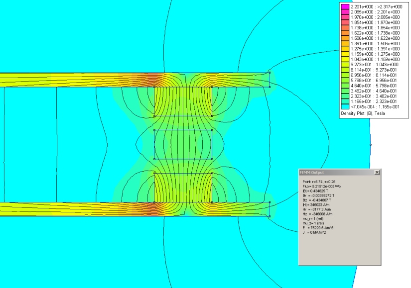
3179-0

vs. this...

3180-1

As I have mentioned to RP, and again not to sound glib,- have you tried this and found no increase in output, or in fact a reduction in output? It might be that ~'all' of the (useful) flux is already channeled in the other (angular) plane/direction. I am OK with that, just looking to hear that / see that someone has thought of this, tried this, recorded this, prior to building it and charting output vs. my current build. Afterall, the reason my rotors are steel and not plastic, rubber, wood, is that someone (Hugh) gave me that advice.

It may come down to building another stator for a few reasons - that in the medium term anyhow - which is OK too.

Since all of my connections are outbound from stator, the reality is that I'd have to -

1) Disassemble and build the ring on the inside, as close to the magnets as possible and without coil intereference.
2) Re-wire, pour and mount stator so that the connections run inbound toward shaft.

#1 would be more scientific, since I would have results of adding the perimeter steel vs current.
I don't mind #2) either though, since I could then loose the 1/8" plexiglass on each side of the stator.
Will model that later this afternoon. I am almost certain there will be a B gain there.
There would also be a gain in flywheel effect with the additional steel perimeter.

 
Marble cake is hard on the teeth.

SparWeb

  • Global Moderator
  • Super Hero Member Plus
  • *****
  • Posts: 5452
  • Country: ca
    • Wind Turbine Project Field Notes
Re: Bicycle Generator Project
« Reply #61 on: May 27, 2011, 04:39:52 PM »
Strangely, I have, actually.

The problem is trying to model 2D in something that is 3-dimensional.  You tend to draw only the things on the plane and ignore the things that are there, but can't be drawn on the same plane.  I settled for drawing the circumference of the rotor because the flux circuits mostly close that way, in reality and in the model.

The trouble with the model is that it's a cross-section taken along the edge of a cylinder, so it takes some mental gymnastics, and up until now I haven't encountered many folks who care about what I'm talking about.

Your section is a radial section.  Passes from the axis through one magnet.  Modeled that way, you can't help but think that the material around the edge of the disks or perhaps better around the hub will do a lot of good.

I MADE EXACTLY THE SAME MISTAKE several years ago.

In reality, the flux lines go from magnet to magnet, all the way around.  If the backing plate is too thin, then some flux lines can leak out, and if the plates are too far apart, then the lines can creep around instead of jumping straight across the gap.  IMHO the best solution for too much leakage is thicker plates and/or tighten the gap (if you can).  If I were to model a 16-pole axial-flux rotor, I would make a very wide model, to scale, with 20 magnets along the top and 20 along the bottom.  Ignore the 2 on each end and all of the flux lines are pretty straight and correctly scaled in the remaining 16 poles.  Note that the area of a round magnet is 86% of a rectangular magnet, and the depth of the FEMM model determines how much flux passes through the area, as a rectangle.


Requisite footnotes because 20% of readers deliberately try to misunderstand this and cause 80% of confusion:  I am only talking about the 2-rotor-disk axial flux, where numerous magnets alternate in polarity, intended to be a generator as per Hugh PIggott design.  All other configurations are toys, wastes of time, have different purposes, or something else entirely.
No one believes the theory except the one who developed it. Everyone believes the experiment except the one who ran it.
System spec: 135w BP multicrystalline panels, Xantrex C40, DIY 10ft (3m) diameter wind turbine, Tri-Star TS60, 800AH x 24V AGM Battery, Xantrex SW4024
www.sparweb.ca

jaysicle

  • Jr. Member
  • **
  • Posts: 73
Re: Bicycle Generator Project
« Reply #62 on: May 27, 2011, 10:59:50 PM »
Strangely, I have, actually.

Nice that you have considered this. Did you build it by chance? It is interesting to draw the circumference and understand that the flux circuits 'mostly' close that way.... and I am looking to define that 'mostly" - i.e.: do we have a percentage? If you saw that your model said 15% increase by adding steel around perimeter, but after building it your Gauss meter read 4%, then that is awesome. If your model said 15% and you decided not to build it, then that is less awesome, but perhaps wise. I realize that you digging up old information may be as or more difficult than me just trial and error-ing this... I also realize that the topic might be out there somewhere 'real world'd' to death and perhaps proven as 'out'.

As for gymnastics, this is not that complicated - but I do legitimately care about what you are talking about (in an EMF sort of way)  ;) ... and am happy to be one of the few that does ! It might be easier if our eyes and brains could perceive this spectrum I guess. Or, maybe we'd just get headaches more often.

Your section is a radial section.  Passes from the axis through one magnet.  Modeled that way, you can't help but think that the material around the edge of the disks or perhaps better around the hub will do a lot of good.

Well, kind of... that particular FEMM simulation is of a singular pair of opposing magnets with a 1/4" steel backplate although I wrote 'one magnet' above I meant pair. - but no, I don't think that it will do a lot of good, in fact I only think that it might do some good. Some portion of about ~15% good actually. A lot of good would be to adjust the seat so that my relatives could charge the batteries.

If you figure (and it is OK if you do... ) that there is zero flux lost at +/-45-90°, and 90-135° windows to the inside or outside of this rotor type (as top view / dinner plate view) at each pole - then a box of (10) chocolate Timbits must be wagered. I think they would keep in the mail. Actually, we should probably FEMM one of them just for that attribute. If absolute zero is not fair then we need to agree on a percentage - I want the number afterall !

Thank-you for the footnote, I did have faith that most would have looked at the machine I have built and know that it employs an axial flux generator, but - maybe you're right.  ;)  --  As for your understanding... I believe you are on the screws - (golf term - please look it up if not familiar), although I sure could use an empirical answer to my question :-\

I appreciate that you took time to write in my diary, and genuinely respect your experience in these endeavours.
« Last Edit: May 27, 2011, 11:24:33 PM by jaysicle »
Marble cake is hard on the teeth.

ghurd

  • Super Hero Member Plus
  • *******
  • Posts: 8059
Re: Bicycle Generator Project
« Reply #63 on: May 28, 2011, 04:02:44 AM »
Because it is already built, physically check to see if any substantial flux is leaking!

See if a large paper clip will hang on the back of the rotor.
If it will not, or just barely holds it up, then there is no flux leakage worth considering.
If a small screwdiver will not stick to the back, not sure there is enough flux leakage to worry about.

Case in point:
Tiny neo from a HD voice coil, 1/8" diameter x 1/8" long, probably N35 at most.
It easily holds up TWO big 2"x3/8" paper clips with the neo in my fingers, and holds up 3 with patience.
If the neos is stuck to my pocket knife, the neo easily holds up 5 paper clips.  It might hold 6, but I do not have 6 that big.
It easily holds up a 23.3 gram (0.82 ounce) pocket screwdriver.
(photos on request)
G-
www.ghurd.info<<<-----Information on my Controller

ghurd

  • Super Hero Member Plus
  • *******
  • Posts: 8059
Re: Bicycle Generator Project
« Reply #64 on: May 28, 2011, 05:00:39 AM »
OK, I admit I have nothing better to do at 4:30AM until I get accustomed to these goofy work hours.
Photos

5 big paperclips hanging on my pocket knife.


The same 5 big paperclips.  The little neo is on one, and an identical neo is on the tape measure at 2-3/16".


'Everything together'.
The same neo supporting a pocket screwdriver, an identical screwdriver near the tape measure, the paperclips, the pocket knife,
and the identical neo is still on the tape measure at 2-3/16".
Compare the neo on the tape measure to the screwdriver next to it.


That is a tiny little neo.  Weak.  No surface area.  No length.  No volume.

If the back side of a rotor plate can not do better than that, then there is not very much flux leakage!

Side note:  The eBay sellers who brag about how many pipe wrenches the OUTSIDE of their PM DC motor can hold up obviously do not know what they are talking about.
G-
« Last Edit: May 28, 2011, 05:05:30 AM by ghurd »
www.ghurd.info<<<-----Information on my Controller

klsmurf

  • Full Member
  • ***
  • Posts: 158
  • Country: us
  • "Damn it Jim, I'm a carpenter, not an electrican"
Re: Bicycle Generator Project
« Reply #65 on: May 28, 2011, 09:13:39 AM »
Mr. G- or anyone else,
 Could you please help this noob and elaborate a little more on this statement.

"Side note:  The eBay sellers who brag about how many pipe wrenches the OUTSIDE of their PM DC motor can hold up obviously do not know what they are talking about.
G-"

I think I understand, but I have been wrong before ;D
 
PS.   I have one of these motors up and flying now. I see 15A on a 12V system in a 30MPH wind.
" A man's got to know his limitations " ------ Harry Callahan