Using SCR's as a rectifier bridge
Hi All,
This a trackback to another thread and started here-
http://www.fieldlines.com/index.php/topic,146527.msg1003584.html#msg1003584This is a trackback for this thread-
I had a couple more of those SCR's that I dug out of my collection of spare parts.
http://www.allaboutcircuits.com/vol_3/chpt_7/5.htmlhttp://www.fieldlines.com/index.php/topic,146527.msg1003584.html#msg1003584JW
« Reply #15 on: March 15, 2012, 06:55:20 PM »
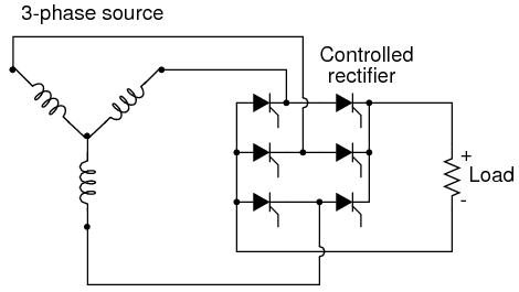
I would use a 50amp breaker (self-reset) for the DC lines... I have also found you can use a 300amp SCR as a rectifier in a bridge configuration (6/w 3phase) for cheaper than the rectifier diode listed, and the thread dia is about a 1/2in to the heatsink, and the trick is to leave the gate termial isolated, in other words you can get a SCR with higher ampere rating for less the cost of a large package rectifier diode...
 http://www.allaboutcircuits.com/vol_3/chpt_7/5.html
Image's from link
*
bvan1941
« Reply #16 on: March 15, 2012, 07:01:47 PM »
jw,
great observation and recommendation on the SCR's !!!
It's usually not thought of that way. Glad to see you point that out
Re: Light Weight Wind Turbine Project - as I build it.
« Reply #17 on: March 15, 2012, 07:10:49 PM »
I have also found you can use a 300amp SCR as a rectifier in a bridge configuration (6/w 3phase) for cheaper than the rectifier diode listed, and the thread dia is about a 1/2in to the heatsink, and the trick is to leave the gate termial isolated, in other words you can get a SCR with higher ampere rating for less the cost of a large package rectifier diode...
*
dinges
« Reply #17 on: March 15, 2012, 07:10:49 PM »
Are you sure about using SCRs as rectifiers? Don't think it works like that. Just grabbed a few large SCRs out of the box and none behave as a diode, with the gate left unconnected.
The link (allaboutcircuits) shows that when the gate is left disconnected it behaves as a Shockley diode (which is a 4-layer diode). Note that this is not a Schottky diode! (which is a 2-layer diode).
If I'm wrong, please correct me
*
JW
« Reply #18 on: March 15, 2012, 07:34:29 PM »
Are you sure about using SCRs as rectifiers? Don't think it works like that. Just grabbed a few large SCRs out of the box and none behave as a diode, with the gate left unconnected.
Well this one does, as you can see from the picture I have my Fluke 88 connected in "diode test mode" with the gate isolated and its passing the diode check...
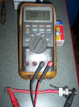
Are you sure to have polarity correct? Im getting a reading of less than one ohm.
*
dinges
« Reply #19 on: March 15, 2012, 07:54:58 PM »
Are you sure to have polarity correct? Im getting a reading of less than one ohm.
Yes, I see. It appears the SCR is defect. Have you tried measuring it with other polarity? (reversing the meter leads)
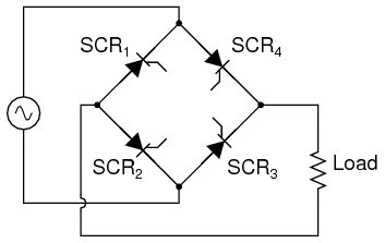
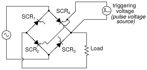
Notice that in the allaboutcircuits article that in the schematic, they talk of controlled rectification; they've left out the electronics to drive the gates of the SCRs, but that's definitely needed to use SCRs as rectifiers (as e.g. in synchronous rectifiers).
Tested a few more known-good SCRs, and all measure fine on the semi-conductor analyzer (with ability to measure the most important parameters of SCRs), but none show any diode action between K and A; which is to be expected, because in that case the Gate would be useless....
My suspicion is that your SCR is defect and is a dead short. By reversing the DMM leads you should be able to verify for sure.
Either that, or my knowledge about SCRs is seriously lacking....
*
JW
« Reply #20 on: March 15, 2012, 08:08:45 PM »
My suspicion is that your SCR is defect and is a dead short. By reversing the DMM leads you should be able to verify for sure.
I just did that, and you are correct its a dead short. interesting.
Just as an aside I abandoned any attempts to use SCR's with the switching arrays im running now, Mosfets when syncronised can give those low impeadance (switching) readings using DC. The problem with SCR's is that they are subject to 0volts threshold, so SCR's work great as diodes when used in the bridge configuration. The schematic's are pretty clear as to DC output. So for the same reason an SCR is no-good for a DC switching application (mosfets n/p channel) it is usable as a rectifier when the gate is not energized.
they talk of controlled rectification; they've left out the electronics to drive the gates of the SCRs, but that's definitely needed to use SCRs as rectifiers (as e.g. in synchronous rectifiers).
Im going to look for where it says the gates need to be rectified to convert AC to DC
*
JW
« Reply #21 on: March 15, 2012, 08:14:10 PM »
aH Ha now I see what you mean
*
JW
« Reply #22 on: March 15, 2012, 08:27:05 PM »
Im just wondering, is it possible to cast a trigger coil in the stator, if anyone wanted to take the leap too-
but that's definitely needed to use SCRs as rectifiers (as e.g. in synchronous rectifiers).
they've left out the electronics to drive the gates of the SCRs,
"synchronous rectification" SCR's are way cheaper than rectifier diodes for current capacity, so if you could make a cheaper rectifier with a simple trigger circuit (cast into the stator) wouldnt that be worth the effort.
Doesnt seem that hard with the 3/4 9/12 coil-magnet-ratio
*
Steadfast
« Reply #23 on: March 15, 2012, 08:40:48 PM »
Ummm.. you guys are hurting my electicity ignorant brain.... I am an expert and even savant in many medias and art forms, but I am a dolphin at a mountian climbers convention when you guys start to talk electric tech like this... please speak to me about electricity and circuits as if I am much more mentally challenged...
See, look under my name... it says "newbie" for a reason...
thanks...
*
tecker
« Reply #24 on: Today at 04:47:42 AM »
Ty the gate to the anode with a signal diode for half wave Rectifier
***
~~~~~~~~~~~~~~~~~~~~~~~~~~~
Beginning of thread----
I decided ok, lets check that out, ie: "tie the gate to the anode" I was pretty optimistic, a diode in series is a halfwave rectifier.
As Dinges pointed out a shorted SCR cant work, he is correct. When the gate is tied to the anode, the SCR conducts in both directions irregaurdless (like its shorted).
What I did find that was interesting, was that a led in series with the connection (gate to anode) caused the SCR to act like a diode. Im pretty sure the arrangement will need a shunt resistor in parallel to protect the diode(led). Im also considering trying other diodes like a 4011 or IN914.
")
")
")
I just find this interesting.
