Author Topic: Axial flux turbine MK 2  (Read 22693 times)

0 Members and 1 Guest are viewing this topic.

karlb

  • Jr. Member
  • **
  • Posts: 57
  • Country: gb
Re: Axial flux turbine MK 2
« Reply #33 on: February 12, 2014, 08:59:21 AM »
Today I recieved my 1kg of clear casting polyester resin. it's a two part mix with catalyst to add.
The instructions say: "The normal working proportion of catalyst is 1% by weight. This can be increased to 2% for very small quantities of resin, or in low working temperatures. Do not use too much catalyst, which may result in the casting becoming cracked or discoloured. A large casting done in one pouring may generate too much heat and crack. Metal and solid objects generally, tend to expand or contract at a different rate from the resin, which can result in a crazed effect."

I've finally convinced myself that I should make a wooden mould to cast the stator all in one pour, rather than use my 3d printed section mould. If I do it in sections then small errors might build up at each stage. I'll just make sure I take careful measurements so that the wooden mould is exact.

I think the size of my stator would be considered as a large casting. So my question is, can I reduce the proportion of catalyst, to something like 0.7% or even 0.5% to make the setting time longer and reduce the risk of cracking? Or do I run the risk of it never completely setting?

KarlB.

electrondady1

  • SuperHero Member
  • ******
  • Posts: 3120
  • Country: ca
Re: Axial flux turbine MK 2
« Reply #34 on: February 12, 2014, 06:43:59 PM »
the ambient temperature plays a major part.
at room temp. i normally reduce hardener by 50% of what ever is recommended


karlb

  • Jr. Member
  • **
  • Posts: 57
  • Country: gb
Re: Axial flux turbine MK 2
« Reply #35 on: February 14, 2014, 11:41:07 AM »
Great. Thanks for the advice. 0.5% catalyst it is then.
Been busy building a mould and on track to cast the stator this weekend  :)
KarlB.

electrondady1

  • SuperHero Member
  • ******
  • Posts: 3120
  • Country: ca
Re: Axial flux turbine MK 2
« Reply #36 on: February 14, 2014, 03:33:54 PM »
mix it together really well,
then mix the hell out of it again
your gonna need lots of ventilation or do it out in a shed or something
 the stuff really stinks and it can make your very ill so

electrondady1

  • SuperHero Member
  • ******
  • Posts: 3120
  • Country: ca
Re: Axial flux turbine MK 2
« Reply #37 on: February 14, 2014, 03:43:42 PM »

the stuff i used was just ordinary resin and hardener .
it wasn't two part + hardener as you mentioned

kitestrings

  • Hero Member
  • *****
  • Posts: 1376
Re: Axial flux turbine MK 2
« Reply #38 on: February 14, 2014, 04:31:08 PM »
karlb,

I don't know if it is similar consistency to the epoxy we used, but I found few things that helped were:

to heat the coils/mold and epoxy mix slightly
put a vacuum on the mold if possible
insert the material using syringes

The latter, in combination with the vacuum will remove a lot of the entrapped air introduced in mixing.

Good luck, ~kitestrings

karlb

  • Jr. Member
  • **
  • Posts: 57
  • Country: gb
Re: Axial flux turbine MK 2
« Reply #39 on: February 14, 2014, 07:39:07 PM »
Thanks for the suggestions guys :)
I have a mould made and 7 coils wound. The coils are about 120 turns each of 22swg wire.
Only 11 more to go.


the stuff i used was just ordinary resin and hardener .
it wasn't two part + hardener as you mentioned
I meant two part including the catalyst, probably wasn't clear enough :)
KarlB.

karlb

  • Jr. Member
  • **
  • Posts: 57
  • Country: gb
Re: Axial flux turbine MK 2
« Reply #40 on: February 14, 2014, 08:52:59 PM »
.
KarlB.

karlb

  • Jr. Member
  • **
  • Posts: 57
  • Country: gb
Re: Axial flux turbine MK 2
« Reply #41 on: February 20, 2014, 08:32:07 PM »
Previous post was an accidental double post.

I now have the alternator fully assembled. Here are the steps I took:
Wound all 18 coils
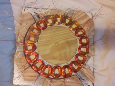
I found a use for my jig in that I could place the coils in it whilst I was fixing them together using fibreglass cloth and superglue. I found that I very slightly overwound most of my coils and they would not fit in the mould easily at the diameter they were supposed to, but at one slightly larger.
A bit of manipulation into the jig squashed them into the diameter that they were supposed to be on, and then I glued them so that they stayed that way.
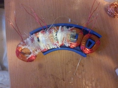
After a while I have all the coils attached together

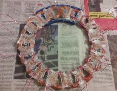
They then go in the mould with strips of newspaper around the outside to wedge them into the right position and keep them there. I used a layer of cling film to make sure I can easily slip the casting out of the mould once set.
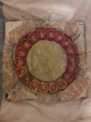
Then I put in the resin with 0.5% hardener added and mixed in thoroughly. The advice from kitestrings on using a syringe to apply the resin was very helpful. The syringe was totally ruined afterwards due to epoxy setting inside it, but they are cheap.
I then placed another layer of cling film and a flat piece of wood on top. Then quite a few bricks to ensure flatness.
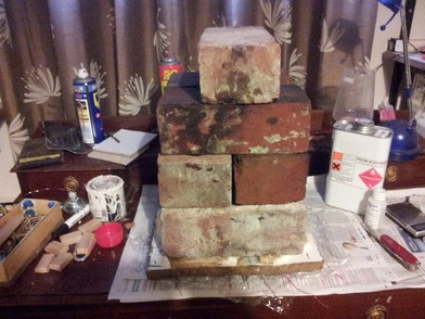
I left it like this overnight and by the next day it was mostly set but still slightly malleable, So I left it for another day. After this it was rock solid but the entire casting had a sticky residue on the outside, maybe this was because the epoxy hadn't entirely set, or maybe it was because I had not mixed it thoroughly enough. Either way, I was not patient enough to wait longer so I removed the residue with acetone. Underneath the residue the casting was fully set and very strong. I think next time I will use something nearer to 0.75% hardener.
Anyway, here I have the completed stator resting on top of the bottom rotor.
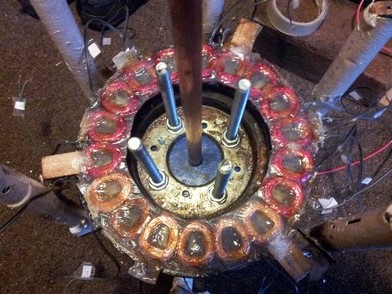
Because I used clear epoxy, I can actually see through the centre of the coils to the magnets underneath, which makes accurately fixing the stator to the frame easier.
I 3d printed four plastic tubes that slide onto the threaded rods and act as spacers. This way I don't have to worry about screwing four nuts up and down threaded rods until the top brake disk is level, I just tighten the nut up to the tube and I know that all four tubes are the same length. I can file down all the tubes equally to reduce my air gap.
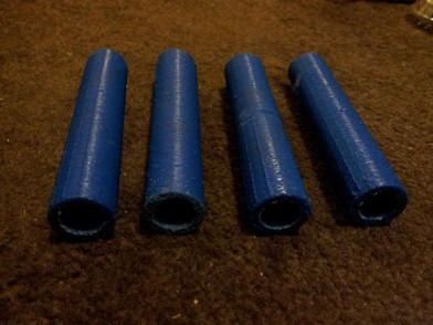
Here is the assembly minus the top brake disk with the tubes spacing the nuts:
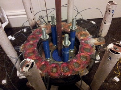

After adding the top brake disk and adjusting everything it's time for some testing.
Open circuit I get 12v at about 130rpm and 18v at about 200rpm.
Short circuit current is about 0.5A, which is the most I can do by hand, above that it gets very difficult to turn. I imagine a bike or windmill would be able to apply much more torque.
I think that the cut in speed is a bit high for a VAWT. What do you guys think? I have enough clearance to reduce my airgap by about another 1mm so I will try that.
But also I think my wiring is non standard. It's not star or delta, I don't even know if this has a name:

One full wave rectifier for each phase and then each rectifier is connected in series. I did this because I built my 3 phase rectifier a while ago when I was less educated.  Is this arrangement inefficient and would re-wiring to star give me a higher voltage? I have the wires exposed for each individual coil so I can play around as much as I want.

Thanks
« Last Edit: February 20, 2014, 08:39:28 PM by karlbaker »
KarlB.

electrondady1

  • SuperHero Member
  • ******
  • Posts: 3120
  • Country: ca
Re: Axial flux turbine MK 2
« Reply #42 on: February 21, 2014, 09:44:59 PM »

tune it up and see what you get?
i think it's a bit fast for a drag vertical
a little better for a Darrieus lenz2 or H rotor
and probably  good for a hawt
but that's not my area of expertise.


you are running what used to be called rerryrigged or individually rectified phases but the output is normally run in parallel
not sure about the rectifiers in series.
 that might be pulling down more than 1.4 volts
if you rewire to star it will give more volts at a lower rpm but the phase resistance will go up.

consider single phase as a way to produce a charging voltage at a lower rpm.
for drag mills it allows a charging voltage at a lower rpm and maximum amps.

what sort of wind resource do yo have?


joestue

  • Hero Member
  • *****
  • Posts: 1763
  • Country: 00
Re: Axial flux turbine MK 2
« Reply #43 on: February 22, 2014, 12:16:00 AM »
the only reason to rectify the phases separately like that would be to run each one into dc-dc converter, with a PFC front end. (note this is actually doable, because most of them will work from 60 to 250vac)

without something like that, you would be wasting heat in unnecessary diodes. a star winding would deliver more volts and the same current, all three phases in parallel would be the same as a delta connection.. the only reason to use three separate bridge rectifiers is if the waveform is so bad that 3,5,7,9 harmonics are causing non negligible voltage cancellation and circulating current
My wife says I'm not just a different colored rubik's cube, i am a rubik's knot in a cage.

electrondady1

  • SuperHero Member
  • ******
  • Posts: 3120
  • Country: ca
Re: Axial flux turbine MK 2
« Reply #44 on: February 22, 2014, 08:22:30 AM »
if you search the members list for Jerry you will find a prolific builder and experimenter who came up with a different winding method
the debate went on for months but in the end Jerry proved his point
 if you wind coils so that each phase gives the voltage you want at the rpm you want and rec.  separately, you  end up pulling more watts and running cooler.

his and windstuff eds work led to my own experiments with two phase. 
 
« Last Edit: February 22, 2014, 08:30:37 AM by electrondady1 »

joestue

  • Hero Member
  • *****
  • Posts: 1763
  • Country: 00
Re: Axial flux turbine MK 2
« Reply #45 on: February 22, 2014, 01:01:17 PM »
But he was running three different Vrms coils rectified in parallel.
My wife says I'm not just a different colored rubik's cube, i am a rubik's knot in a cage.

karlb

  • Jr. Member
  • **
  • Posts: 57
  • Country: gb
Re: Axial flux turbine MK 2
« Reply #46 on: February 22, 2014, 11:02:35 PM »
I've read up on the experiments of Jerry and others on individually rectified phases.

I can see how this would give less voltage, as you are using more diodes, so a bit more voltage is lost due to voltage drop.
Rewiring to star seems to give me little to no extra voltage. This is probably due to the small gain I get being outside of my measurement accuracy range. I'm hand cranking the generator with a bike speedo for rpm measurement, and keeping it dead on 200 rpm is difficult. I can get within +/- 10rpm which gives +/- about 1 volt.
I'll keep it in star, because at least in theory I know it should give more voltage.

There is a mention in one of the threads about connecting the star point to a fourth rectifier and then paralelling the output of that to the dc line. I thought it was worth a try, but it doesn't give me anything extra. The star point is supposed to be neutral anyway so this would only offer a gain if the phases were not perfectly aligned and you had a bad waveform and harmonics like joestue said.

I still have yet to tune up the machine. Looks like there's only about another 1mm clearance left in the airgap so things will be difficult.

One thing to note is that two of my phases are producing 8 volts output at 200rpm and one phase is producing 5.5v. I've tested each individual coil and they are all putting out voltage. I didn't count my turns and only judged whether coils were full based on their width so maybe that phase just ended up with less turns.

With no other options, it looks like I'm going to have to build a lift type VAWT or a HAWT in order to extract a charging voltage. This thing is big and heavy, so mounting it on a HAWT would be awkward, probably slightly unsafe, and look weird. So I'm left with the option of having the generator on the ground, with a rotating shaft going up to a lift type VAWT.
My average wind speed in this area is 10.5mph according to online historical weather information.

consider single phase as a way to produce a charging voltage at a lower rpm.
for drag mills it allows a charging voltage at a lower rpm and maximum amps.
I understand. But am I stuck with 3 phase unless I cast another stator?

Another unrelated question; does anyone else notice a small voltage coming from their generator even when it is completely still? I'm picking up around 0.1 - 0.2 volts, and the multimeter goes to 0 when I disconnect it, so I know it is definitely there. Is it due to background emf being picked up by my coils and then being rectified?
KarlB.

electrondady1

  • SuperHero Member
  • ******
  • Posts: 3120
  • Country: ca
Re: Axial flux turbine MK 2
« Reply #47 on: February 23, 2014, 10:33:25 AM »

i think this alternator is a huge  improvement over your first one
200 rpm is about as fast as a drag mill tuns even in a gale
you want to get a charging voltage at some fraction of that .

on that low voltage phase, check that no coils are flipped and wired in reverse .
that happens all the time.
 without accurate turn count on your test coil your kind of whistling in the dark.


having just built the thing , give yourself some time.
 if you go as is , consider 6 volt battery storage.
or a pulley to a big vawt and over drive the alternator

your now at the very stage i was about ten years ago having built 2 three phase alternators that didn't produce in the way i wanted.  i decided to go with single phase for my low speed vertical mills.
with three phase your basically using 1/3 of the coils at any one time to produce your voltage .
i reasoned at the speeds i was working with i needed all my mags to make voltage.
i just took a hammer to the stator and reclaimed all the copper. :'(

 decided i wanted 14 volts @60 rpm
and started doing test coils.
14volts +1.4 rectifier voltage drop, /1.4 rectify to dc /20 coils=5.5 volts per coil

with three phase in star
14 volts+ 1.4/1.4 /1.74/9 =1.2 volts per coil

keep us posted on what your doing next.


karlb

  • Jr. Member
  • **
  • Posts: 57
  • Country: gb
Re: Axial flux turbine MK 2
« Reply #48 on: February 23, 2014, 04:41:45 PM »
I did another test on the low voltage phase and found that I did indeed have a coil flipped. Thanks for the suggestion. Cant believe that I didn't notice before.
I can now get 18v at 180rpm which is better. And my 12v battery charger can fully charge from a supply voltage of 16v so maybe that's what I should be aiming for. If so then that means I only need 160rpm.

In terms of blade design, I still have the small savonius blades left over from my last build which you can see in the video in my sig.
I think I will build some H shaped darrieus blades about twice as tall and twice the diameter of the existing savonius blades, but then add in the savonius blades on top or in the middle to assist startup in low wind speed. Making it a hybrid savonius/darrieus.

I will take a bit of time to think about design and source materials before the next phase of the build, but I'll make sure I keep you posted.
« Last Edit: February 23, 2014, 04:48:10 PM by karlbaker »
KarlB.