Old topic, I know... but thought I'd drop a few lines anyway.
About the shape of the coils... it seems nobody has mentioned this to you yet, so I'll try.
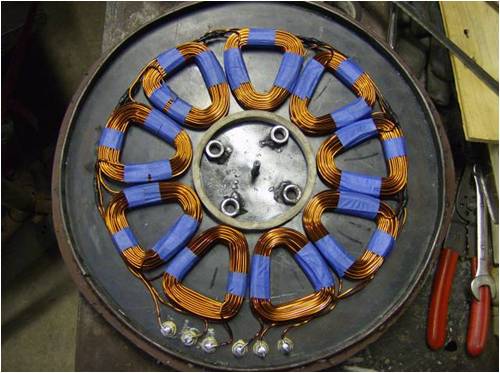
The idea is to make them the shape such that one "side" of the coil picks up the magnetic flux from one magnet, while the opposing side of the coil gets its flux from the neighboring OPPOSITE polarity magnet.
Here's why...
When you pass a single wire across the face of a magnet (parallel to the length), that single strand of wire creates a voltage that follows what's called the "Right Hand Rule". Imagine grabbing that wire in the palm of your hand, wrap your fingers around it, then point with your thumb following the direction of the wire... your thumb will indicate the direction of electron flow.

Now, consider you have 100 strands (100 coil turns) of wire in your hand = 100 times the electron flow.
Now, let's assume you began with your hand grabbing one side of your coil, positioned such that your thumb was pointing towards the center of your Stator.
Now if you were to loosen your grip a little, and slide your hand around the coil to the opposite side... which direction is your thumb pointing? It's pointing to the outside of the Stator, right?
This means on one side of each coil you need a (for example) North pole under it to get the current flowing (for example) counter-clockwise; then to continue the counter-clockwise flow the opposite side of the coil needs a South pole under it.
This is why it was mentioned that you need the coils formed into a trapezoidal (or triangular) shape, so that it will be intersected by the flux from two neighboring magnets. This all applied for rectangular and trapezoidal "wedge" shaped magnets.
 NOTE:
NOTE: This all assumes
CORELESS coils... as in the Axial Flux Coreless Alternators. (no ferrous core material)
Once you put a core in the coils, the whole design goal changes... and it becomes a totally different machine, with totally different set of design rules... and less applicable to wind turbines and low (non) cogging alternator goals. (the coil with core then needs to cover the face of just one magnet, because the ferrous core material focuses all the flux up through the coil in one uniform direction - quite the opposite of the coreless design)
Depending on the magnet-to-coil ratio, in many coreless axial flux alternators, adjacent coils will "share" magnets, simultaneously. This is why it was also mentioned that you should keep the sides of the coils shaped "cleaner", less curvy, so that two adjacent coil-sides will fit over each of your rectangular magnets. In multi-phase alternators, you may not have as much overlap, if any.
The "inner" and "outer" ends of the coils must be past the edges of the magnets... you do not want the perpendicular edges of the coils passing over the magnetic fields... avoid this as much as possible anyway.
Using two magnet-carrying rotors (with magnets in N-S attraction alignment), forces the magnetic flux to cross through the coils between the magnets. Otherwise, with a single magnet rotor, each magnet's flux will be trying to "return" to the closest opposite magnetic pole it can find... be it its own, or of a neighboring magnet. This is also why ferrous backing plates behind the magnets help... it creates a "shorter return path" for the flux, enhancing the strength of the flux crossing through the coils. Magnetic flux always seeks the "path of least resistance"... called reluctance. Air has a very high reluctance, ferrous materials have low reluctance.
FWIW - the first post in the following thread shows a neat "coil" design for a 3-phase axial flux alternator:
http://www.thebackshed.com/forum/forum_posts.asp?TID=1484