Author Topic: Christmas Windmill Time  (Read 29113 times)

0 Members and 2 Guests are viewing this topic.

taylorp035

  • Hero Member
  • *****
  • Posts: 1206
  • Country: us
  • Stressed spelled backwards is Desserts
Re: Christmas Windmill Time
« Reply #198 on: October 21, 2021, 06:10:43 PM »
Here is the potting compound before it dried and I took the tape off.

14380-0


And here is my new battery pack compared to the old one.  I decided to spring for the battery holders, which are super nice.  99 Tesla model 3 cells, tested at over 4600 mah each.  Should be good for about 1.5 kWh.  The next challenge is to pull off my series/parallel switch and wiring + adding in some Eaton 2.5A slow blow fuses to each cell and probably some big fuses on each 33 cell section if I mess up.  I want to be able to run a 1500W device, particularly my fridge in a power outage.  I have a 2000W inverter picked out, but I want to make sure I have my wiring ready to handle such loads, while also being able to connect easily to my 150w mini inverter + the windmill.  I think I want to have some separate 6 AWG or larger wires going to the inverter and some larger 100-150A capable connectors.  It would be cool if I could find some mini 3 pole knife switches so I can do the same arrangement as my first battery pack.

The pack should weigh about 15lbs, so it's still very portable when swapping it out in the windmill.   It will be nice to have two packs so I always have one set charging.

14381-1

SparWeb

  • Global Moderator
  • Super Hero Member Plus
  • *****
  • Posts: 5452
  • Country: ca
    • Wind Turbine Project Field Notes
Re: Christmas Windmill Time
« Reply #199 on: October 21, 2021, 09:26:27 PM »
Where did the rack for those cells come from?  Is it 3d printed?
No one believes the theory except the one who developed it. Everyone believes the experiment except the one who ran it.
System spec: 135w BP multicrystalline panels, Xantrex C40, DIY 10ft (3m) diameter wind turbine, Tri-Star TS60, 800AH x 24V AGM Battery, Xantrex SW4024
www.sparweb.ca

taylorp035

  • Hero Member
  • *****
  • Posts: 1206
  • Country: us
  • Stressed spelled backwards is Desserts
Re: Christmas Windmill Time
« Reply #200 on: October 21, 2021, 10:48:42 PM »
Where did the rack for those cells come from?  Is it 3d printed?
  They are injection molded pieces you can buy for $0.08 per two holes.  So I needed 100 of them.  They also sell them in 18xxx size as well and the fuse sheet that you can directly spot weld to the cells with minimal effort.  I used batteryhookup.com... they recycle mostly lithium ion batteries in Pennsylvania and they have really good value for most of their cells.  They are usually 20-50% the price of a new cell and often times the cells have very few or no cycles on them.  These model 3 cells would of been about $5-6/cell new and I got them for a little over $2.  My blue cells were about $1.25 a piece and they would of been a good $5+ new.

taylorp035

  • Hero Member
  • *****
  • Posts: 1206
  • Country: us
  • Stressed spelled backwards is Desserts
Re: Christmas Windmill Time
« Reply #201 on: November 07, 2021, 07:54:25 PM »
The windmill is now back on the tower and everything is installed.  I torqued the blades a second time a day later, which as I expected, they had loosened up quite a bit.  I also installed my new tower bearings on the bottom of the box so it doesn't rub up against the pole.  it now swivels really nicely.  The whole thing also got a paint job, something that it never had last winter.  All of the electronics were fixed in it as well, so now my power meter reads again and keeps track of my production.  I also fixed up my old battery packs and put them back in their case.  The new battery is partially done, as I received my new spot welder and it's looking pretty good so far.

Now the bad news.  The windmill doesn't want to spin.  Which is highly disappointing considering the amount of work that has gone into this over the last year.   There appears to be two problems.  The first is the magnets are rubbing on the inside of the stator since the whole box isn't as straight as it was when it was on my workbench.  This problem is solvable, as the magnets just need to wear away the material a bit like when I did my bench testing.  I'm fairly confident this will be easy to solve once there's a bunch of wind to get it spinning.  The second problem is the cogging from the magnets being attracted to the shims is quite strong.  I was out there yesterday and it didn't want to start up in ~12-ish mph winds.  Even if I grabbed the blades and gave it a good spin by hand to get it going, it still didn't want  to take off and run.  I was fairly surprised it didn't want to take off even once it was going.  I'll be waiting for the next windy day to see if I can get it going.

I really don't want to make a bigger blade set for several reasons, including over-loading the current tower setup, clearance to the guy wires and the amount of effort and time it takes to carve new blades.  I thought it wasn't too terrible to spin over on my workbench once it loosened up and I figured the extra ~4 degrees of pitch to the blades would really boost the start up performance.  It's also setup as a 4:3 (12 coils vs. 8 magnetic poles), so it's not like all of the magnets are being attracted to the steel shims all at once.
« Last Edit: November 08, 2021, 03:41:19 PM by taylorp035 »

SparWeb

  • Global Moderator
  • Super Hero Member Plus
  • *****
  • Posts: 5452
  • Country: ca
    • Wind Turbine Project Field Notes
Re: Christmas Windmill Time
« Reply #202 on: November 08, 2021, 10:43:40 PM »
Oh dear.
This is probably solvable, but I wouldn't be too optimistic about wearing away the stator for a while, especially if it isn't spinning at all.

Different approach, and unfortunately this means taking it all apart.

How about removing the rotor and using sandpaper spinning on a drum to clean up the inner surface of the stator?
When that's done, can you mount the rotor inside, secure the stator on the bench, and do some load tests?
Wrap a string around the shaft and measure the force to pull - keeping a constant velocity - with a spring-scale.
Push laterally on the end of the shaft, using a dial indicator or a similar sensitive measurement device to find the lateral deflection of the shaft for a given lateral force.
No one believes the theory except the one who developed it. Everyone believes the experiment except the one who ran it.
System spec: 135w BP multicrystalline panels, Xantrex C40, DIY 10ft (3m) diameter wind turbine, Tri-Star TS60, 800AH x 24V AGM Battery, Xantrex SW4024
www.sparweb.ca

taylorp035

  • Hero Member
  • *****
  • Posts: 1206
  • Country: us
  • Stressed spelled backwards is Desserts
Re: Christmas Windmill Time
« Reply #203 on: November 09, 2021, 09:54:54 PM »
Quote
This is probably solvable, but I wouldn't be too optimistic about wearing away the stator for a while, especially if it isn't spinning at all.
-  It worked the first time, so I think it will work the second time, in which this is much less severe then when I first assembled the rotor.   I think what did it in was I had originally clearanced the stator with the main pillow block bearings for the shaft not tightened to the box.  I then tightened it, which caused the shaft to move downwards and is probably squeezing the stator to the bottom board.   You can hear it rubbing for 1/3 rd of the revolution.   I might try to shim up the bearings a fraction of an inch to improve the situation.

Quote
How about removing the rotor and using sandpaper spinning on a drum to clean up the inner surface of the stator?
- Yes, this is what I did originally to help clearance it with a large degree of success.   I have a 2" mini-drum I can put in my coordless drill and quickly remove material from the inside.  I could do it again, but at the risk of breaking the stator and its flimsy flanges.

It's supposed to be much windier on Thursday, with a predicted 19 mph.  Yesterday I went out at lunch and there was more like 14-15 mph winds instead of 12 mph on the first day.  I spun the blades up by hand and it took off two or three times for a few seconds over-coming the friction.  I just need more wind so it does more of that.   I also flipped on the battery one of the times, but that quickly slowed the blades down.  It read a quick 40 watts.   I don't have any weight on the tail, so it should be extra safe from getting away from me.  The blades seemed better balanced than before, but I think I need a more steady situation to evaluate that.

taylorp035

  • Hero Member
  • *****
  • Posts: 1206
  • Country: us
  • Stressed spelled backwards is Desserts
Re: Christmas Windmill Time
« Reply #204 on: November 12, 2021, 01:44:35 PM »
I made a few adjustments to free up the alternator from rubbing internally. It's not at 100% yet, but much better.

Today we received a bunch more wind.  Something to the point where it would of been almost furling on the old setup.  The blades are clearly stalling really bad, like make a TSR of 1-1.5.  I want to re-wire it so it takes off and doesn't load it down so early when it tries to get moving.   In stiff 15-20 mph gust, it maxed out at about 20 watts, usually more like 5 watts.  It wasn't exceeding 120 rpm I don't think, which lines up with my bench testing.

At one point let it spin up and then re-connected the battery.   It spiked at 310 watts, but very rapidly slowed down..

I'm also dreaming up a cam roller follower device to make a cogging torque that is opposite of the alternator (24 peaks) so it starts up easier.  In 22 mph winds last night, it spun a half a revolution and then got stuck again.

MagnetJuice

  • Hero Member
  • *****
  • Posts: 558
  • Country: ca
Re: Christmas Windmill Time
« Reply #205 on: November 12, 2021, 05:43:36 PM »
I would just add a little resistance to the line instead of rewinding.

I think that would be the simplest way to lower the efficiency of the alternator and match it to the power of the blades to keep it from stalling.

Ed
What can I do TODAY that would make TOMORROW a better world?

taylorp035

  • Hero Member
  • *****
  • Posts: 1206
  • Country: us
  • Stressed spelled backwards is Desserts
Re: Christmas Windmill Time
« Reply #206 on: November 16, 2021, 07:50:18 PM »
Quote
I would just add a little resistance to the line instead of rewinding.
I'm going to give this a shot.  I did the math and it looks like the full system currently is about 0.8 ohms.  I just added a coil of 19 gauge wire that is about 1.1 ohms to it after the 3-phase rectifier.  Calling for 18 mph winds tomorrow, so I'll see how it goes.  It should furl before I set my new coil of wire on fire....

I'm still expecting to re-wire it so it can have a cut in speed that's twice as high.  The wires are external of the potting compound, though I soldered and heat shrinked them, so it will be a bit of work to make all 4 coils per phase be in parallel.

taylorp035

  • Hero Member
  • *****
  • Posts: 1206
  • Country: us
  • Stressed spelled backwards is Desserts
Re: Christmas Windmill Time
« Reply #207 on: November 17, 2021, 05:58:34 PM »
The added resistance did very little in helping it get up to speed today.  In heavy winds, it made the same 2-20 watts of power.  If I unhook the battery, it spins up like it used to (~400 rpm), if not a bit better due to the steeper pitched blades.  Loaded it's at about 80-100 rpm.  I'll definitely be re-wiring it now, though I would like to not take it off the tower, so I'll probably do the soldering in position.

I also decided I need to constrain the alternator better rotationally, as it it's rattling a bunch and that's certainly wasting a good bit of power, as well as fatiguing all my wires.  Meanwhile, I did the design work for my anti-cogging device to generate the negative cogging force with a spring loaded roller-rocker setup.  It's a 24 lobe design and should be adjustable up to about 3.3 ft*lbs of cogging torque if my math is right.

14464-0


taylorp035

  • Hero Member
  • *****
  • Posts: 1206
  • Country: us
  • Stressed spelled backwards is Desserts
Re: Christmas Windmill Time
« Reply #208 on: November 17, 2021, 09:55:20 PM »
I went out in the dark tonight to watch the windmill since there were 20+ mph gusts out there.  Ended up doubling my previous record to 41.9 watts at 10.9 amps.  It still didn't take off, even with the added 1.1 ohms.  Based on my bench testing, at peak power the TSR was about 1.5 to 2.  When I disconnected the battery again, it spun up to an easy 300 rpm with no load in 10-15 mph winds and ~450 rpm (33 volts unloaded @ 14 rpm/volt) when it got windier.

SparWeb

  • Global Moderator
  • Super Hero Member Plus
  • *****
  • Posts: 5452
  • Country: ca
    • Wind Turbine Project Field Notes
Re: Christmas Windmill Time
« Reply #209 on: November 17, 2021, 10:49:47 PM »
I'm starting to wonder if other factors are at play.

Cutin is at 75 RPM (you measured this in October) and the current rises linearly to 10 Amps at 175 RPM.  Connected to the 4V battery the generator is producing 40 Watts, probably needing at least 80 Watts mechanically to produce it.  The rotor is big enough to generate this from the wind, so I don't think its the aerodynamics/mechanics causing this.

Earlier this year you adjusted the pitch of the blades.  Have you kept them that way?  Can you tell us more exactly what pitch the roots and tips are at, now? 

Did you add resistance to the AC wires or the DC wire?  Would you like to add more resistance?

Not sure where to look - just casting a wide net.
No one believes the theory except the one who developed it. Everyone believes the experiment except the one who ran it.
System spec: 135w BP multicrystalline panels, Xantrex C40, DIY 10ft (3m) diameter wind turbine, Tri-Star TS60, 800AH x 24V AGM Battery, Xantrex SW4024
www.sparweb.ca

taylorp035

  • Hero Member
  • *****
  • Posts: 1206
  • Country: us
  • Stressed spelled backwards is Desserts
Re: Christmas Windmill Time
« Reply #210 on: November 18, 2021, 07:46:03 PM »
Quote
Earlier this year you adjusted the pitch of the blades.  Have you kept them that way?  Can you tell us more exactly what pitch the roots and tips are at, now? 
- Previously it was 4.5-5.5 degrees at the tips.  I added about another 4 degrees by changing the attachment point to the hub (~1/4" over 4"), so the whole blade is now that much steeper.

Quote
Did you add resistance to the AC wires or the DC wire?  Would you like to add more resistance?
  - Post rectifier, so the DC wires before it goes to my charging circuit.  I would be willing to add more resistance, but I need to do some digging to find something that's appropriate without causing a risk of lighting it on fire at ~30+ amps when she decides to take off.  I'm guessing another 1 ohm would be a good step.


I think I'm roughly at the lower red arrow at cut in and when it gets up to ~20-ish watts, it gets to the end of the arrow.  If I double the cut-in voltage, I'll start at the second red arrow and see a dramatic increase in blade torque.  The downside is it's going to now have 4 coils in parallel instead of 2x2, which will hit harder once it's starts to charge.  Adding some resistance should help once I get to this point.
14468-0

MagnetJuice

  • Hero Member
  • *****
  • Posts: 558
  • Country: ca
Re: Christmas Windmill Time
« Reply #211 on: November 19, 2021, 02:48:26 AM »
You can make heavy-duty resistor coils using nichrome wire.

This is the best stuff to use to make your own homemade power resistors for any high power testing, including for making your own dump load resistors.

You cannot solder nichrome, but you can clamp it tight to a bolt using nuts and washers. If you use a large alligator clamp on one end of the resistor, you can vary the resistance that you add to the alternator, just like having and adjustable resistor. You can find out exactly how much resistance to add to the alternator to match it to the blades.

You can buy it here,

https://jacobs-online.biz/nichrome_v_wire.htm

They are a small business from Washington and have free shipping to the US. I have bought from them before, nice people.

Ed
What can I do TODAY that would make TOMORROW a better world?

MagnetJuice

  • Hero Member
  • *****
  • Posts: 558
  • Country: ca
Re: Christmas Windmill Time
« Reply #212 on: November 19, 2021, 02:55:36 AM »
The problem that you are having with the stalling could also be caused by a coil or two shorting out.

I don't know if you have access to the coils terminals to measure the resistance of the individual coils.
What can I do TODAY that would make TOMORROW a better world?

taylorp035

  • Hero Member
  • *****
  • Posts: 1206
  • Country: us
  • Stressed spelled backwards is Desserts
Re: Christmas Windmill Time
« Reply #213 on: November 23, 2021, 08:57:57 PM »
Quote
The problem that you are having with the stalling could also be caused by a coil or two shorting out.
  I can check that, but I went through a lot of effort to make sure that was never going to happen again by adding 3 layers of insulation on top of the two layers of insulation between coils and shims and then potting the whole thing.

I did some math today to try to better show why I think re-wiring the alternator will work better and get me into a zone where the blades won't stall so much.  I included regular drag from the bearings (0.1 * rpm in watts) and the diode voltage drop (4 volts out vs. 4.7 volts in).  The power graph uses the same 30% efficient blade assumption, which I accounted for in my CP plot.

It seems to show I was hitting a wall where my real CP was probably less than 0.1 and my requirements were in the 0.3-0.5 range to get over 100 RPM.  If I can get closer to a TSR of 4 before cut in, then the blades will be at a much more efficient speed.  I'm assuming I'm crawling up the left side of the plot on my Nov. 18th post on the beta = 7 degrees line roughly.

14483-0

14484-1
« Last Edit: November 24, 2021, 05:13:06 PM by taylorp035 »

taylorp035

  • Hero Member
  • *****
  • Posts: 1206
  • Country: us
  • Stressed spelled backwards is Desserts
Re: Christmas Windmill Time
« Reply #214 on: December 02, 2021, 09:53:53 PM »
With the 0.8 ohm resistor still in line, today the windmill broke its max power record at 74 watts and 18.6 amps.  If I account for the I^2*R losses in the extra resistor and the coils of the alternator, this means it also made about 550 watts of heat, making it roughly 11% efficient electrically.  I'm not too bothered by this, but just an interesting calculation.  I can't wait until I get rid of the resistor and rewire it... which should make it much more efficient.

This also means it made quite a bit of shaft power during that wind gust.  I watched it a little earlier  when it hit 59 watts and it still looked like it was quite low on TSR.  If I did some rough numbers, it worked out to a 20% blade efficiency at about 425 rpm and ~25 mph (12 m/s).... which seem about right based on my original power curve.

I also worked on the anti-cogging device a bunch tonight, so I'm expecting to install it tomorrow.  For reference, in winds that made 50 + watts, it still wouldn't start up by itself.
« Last Edit: December 02, 2021, 10:50:19 PM by taylorp035 »

taylorp035

  • Hero Member
  • *****
  • Posts: 1206
  • Country: us
  • Stressed spelled backwards is Desserts
Re: Christmas Windmill Time
« Reply #215 on: December 21, 2021, 10:54:15 PM »
 I installed the anti-cogging device.  It didn't work like I was hoping.  It only slightly improved the start up torque (~10% improvement) and it only lasted a day before the cam lobe wore out due to fatigue.

14555-0

My rather accurate measurement device for measuring start up torque.  As you can see, it's pretty bad to stop 16 oz of water at a distance of 40".  The cogging rotor dropped that to about 36".  Unfortunately, it could be even worse at one spot of the rotation where my magnets were rubbing in my alternator, bumping this up to something closer to 60".
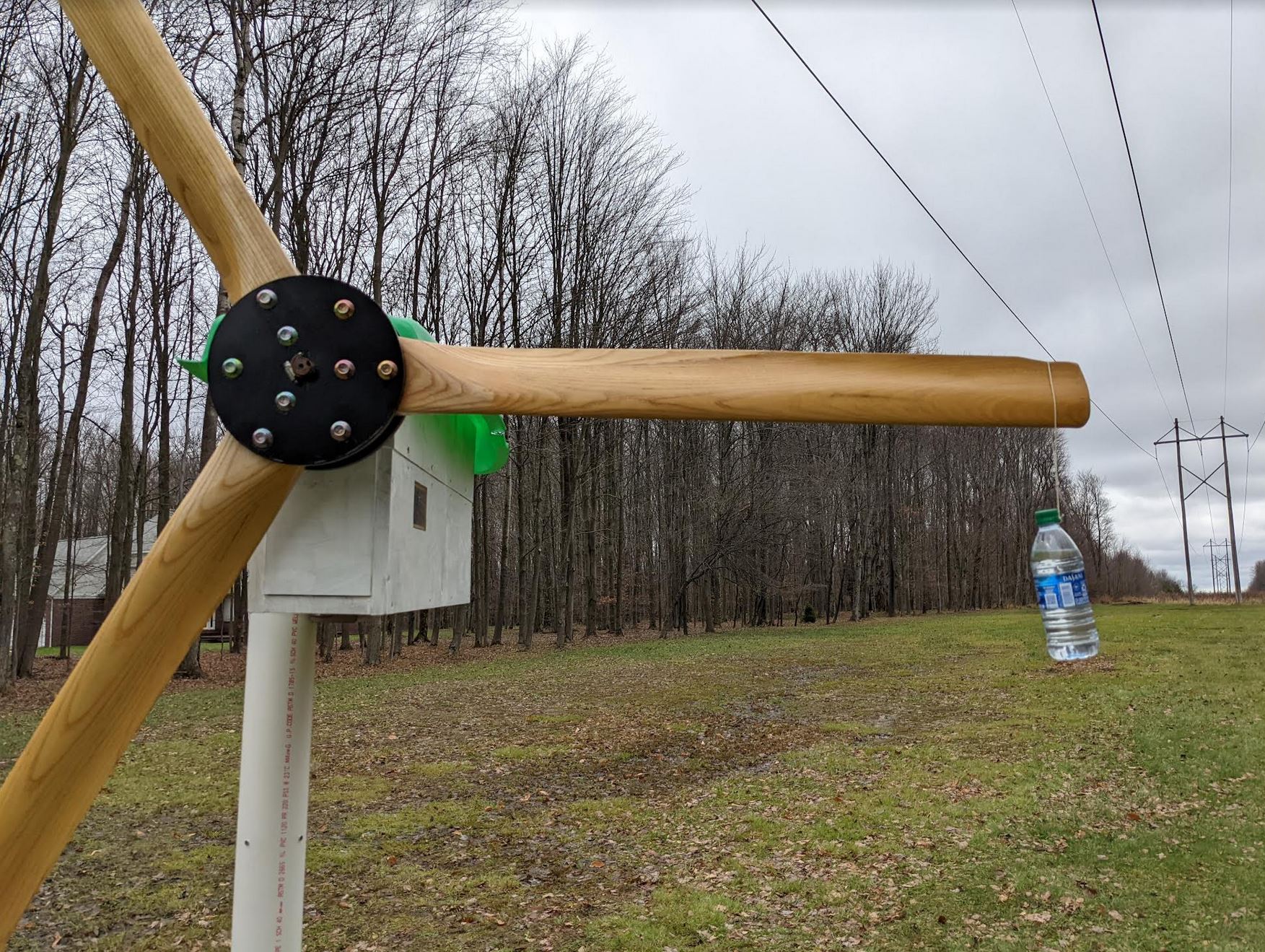
14556-1


So I did what I didn't want to do and decided to bring the whole thing back inside.  It's a real bear to lift it two feet above the top of the tower since it weighs ~ 100 lbs, even with 3 people.  I had spent about 8 hours outside the one day on a ladder messing with different things to improve the start up torque, but it ended up not bearing any fruit.

Once inside, I decided it was time to rewire it.  So today I drew out my current and new layouts on paper and got to work changing the wires around.  It actually turned out to be rather easy.  Now all of the coils are in parallel in each phase (12 coils, 3 phase, 4x1 for each phase of 17 gauge, 68 turns).

Before and after wiring it, I did some more thorough bench testing, both with my extra 0.8 ohm resistor in line and without it for the 2x2 configuration and then later with just the 4x1 coil setup.  I hooked it up to my new battery I just finished, which is ~1.7 kWh of used 21700 Li-ion cells from a Tesla Model 3.  I have hot-swappable plugs so I can change it from 99 cells @ 3.7 volts to 33 x 3 cells at 11.1 volts.  So today's testing was done in parallel mode @ ~455 Ah of capacity.

To drive the hub, I used a DeWalt 20v brushless drill (model DCD790) in low range (600 rpm max).  DeWalt's website claims it can do 360 watts at the chuck at it's peak RPM/load point... of course they don't list what that RPM is. But at least I have a ball park of what I'm putting into rotor.

I used a GoPro and a piece of tape to record the rotor RPM and my power meter.  I then reviewed the footage and went frame by frame to figure out the exact RPM, which was fairly easy to do with a spreadsheet to calculate everything.

So the first piece of data is the peak power into the battery I measured at full throttle on the drill.  In the original 2x2 configuration and with the resistor, I measured about 72 watts.  With the new 4x1 coil setup, I measured 120 watts.  I think this was mostly due to there being less voltage drop across a particular coil (less I^2*R losses) and minorly affected by the drill being able to make more shaft power at the higher RPM.   Assuming the drill could actually provide 360 watts, that's a generator + charging circuit efficiency of about 20% vs 33%... which seems reasonable considering what I'm doing with all of this low voltage stuff (20% lost right away in my diode, and some sizeable amount lost due to eddy currents in the shims and another sizeable amount lost in the resistance of the connections and other wiring, and some lost in the 3 phase rectifier).

Here's the amps vs. RPM of the 3 different setups.  It follows what I expected.  The original data I took a few months ago is also on this plot to show how that it still lines up pretty good with today's testing.
14557-2

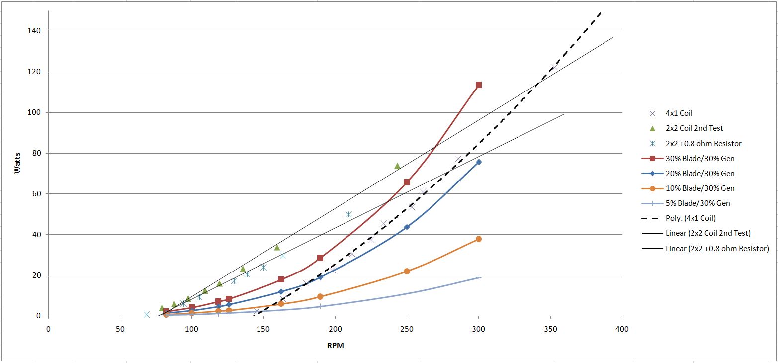
Here's the power vs. rpm.  The black dashed line is the new 4x1 coil configuration.  The lighter thin solid lines are the older 2x2 and 2x2 + the 0.8 ohm resistor lines.
The colored curved lines are scaled values to compare the power available from the blades depending on the multiplier for the generator efficiency and the efficiency of the blades.
This makes it readily apparent that the old setup was never going to work since the generator was even less efficient and the blades never made enough power to match the generator.
The new setup appears that it might just work and spin up to a decent speed so the blades can kick in.
14558-3


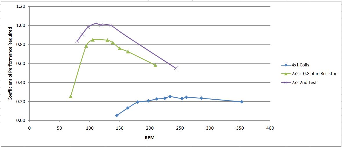
To further bring home this point, here's the calculated blade efficiency required assuming a constant TSR of 4.  Obviously this isn't going to happen in real life, but having a lower value will help.
14559-4


So, what's next?

Well, I still need to fix the start up problem.  After a bunch of thought and my desire to keep things easy and reliable, I think my leading choice is making a dog clutch and governor to control the power going to the shaft.  I would mount it on the front of the hub and then put ball bearings in the two steel discs.  Then the blades can rotate super freely until the RPM gets high enough to engage.  I would probably have it kick in at 180-200 rpm if I can get away with it.

Other options aren't as easy.  Like having a viscous coupling to bleed off a few RPM... but this would be a serious engineering project on many levels.    Another option is to break the shaft in two, push the alternator back and have an electric PTO clutch.  The down side would be the power consumption from the electronics to make this happen and the tuning of such a device.  The third option is to have a motor on the shaft to kick start it when the wind picked up, but that requires yet again more electronics and power consumption.

SparWeb

  • Global Moderator
  • Super Hero Member Plus
  • *****
  • Posts: 5452
  • Country: ca
    • Wind Turbine Project Field Notes
Re: Christmas Windmill Time
« Reply #216 on: December 21, 2021, 11:48:03 PM »
Hi Taylor.
Encouraging to see development on the electrical side.

I have a thought about the cogging.  I see your cam-roller set up that looked like it would add mechanical impulses out of phase with the magnet cog steps.  How about adding a rotor/stator combination that just has magnetic teeth, also out of phase with the cogs of the motor?  As the motor cogs cause a clockwise step, the de-cogging rotor's magnet would be pulling its stator counter-clockwise.  That disk in your photo looks like a good starting point.  You can machine some radial grooves in it, as many as you need to equal the motor's cogging steps.
No one believes the theory except the one who developed it. Everyone believes the experiment except the one who ran it.
System spec: 135w BP multicrystalline panels, Xantrex C40, DIY 10ft (3m) diameter wind turbine, Tri-Star TS60, 800AH x 24V AGM Battery, Xantrex SW4024
www.sparweb.ca

taylorp035

  • Hero Member
  • *****
  • Posts: 1206
  • Country: us
  • Stressed spelled backwards is Desserts
Re: Christmas Windmill Time
« Reply #217 on: December 22, 2021, 07:41:32 AM »
Sparweb - Thanks for bringing up the magnetic solution as well.  I was considering that a little while ago, but I was concerned about how adjustable it would be and how close to a 0 sum torque you could get to.  Also the cost of the magnets to a lesser extent.  I guess you could make it with some smaller magnets and even have a single steel object that could moved to the right location.

SparWeb

  • Global Moderator
  • Super Hero Member Plus
  • *****
  • Posts: 5452
  • Country: ca
    • Wind Turbine Project Field Notes
Re: Christmas Windmill Time
« Reply #218 on: December 22, 2021, 04:12:29 PM »
The price of these magnets should compare well with the cost of a buck controller, and very favourable against a clutch or any other kind of mechanical solution.
Adjust the force by adjusting the spacing between rotor and stator.
No one believes the theory except the one who developed it. Everyone believes the experiment except the one who ran it.
System spec: 135w BP multicrystalline panels, Xantrex C40, DIY 10ft (3m) diameter wind turbine, Tri-Star TS60, 800AH x 24V AGM Battery, Xantrex SW4024
www.sparweb.ca

SparWeb

  • Global Moderator
  • Super Hero Member Plus
  • *****
  • Posts: 5452
  • Country: ca
    • Wind Turbine Project Field Notes
Re: Christmas Windmill Time
« Reply #219 on: December 26, 2021, 01:30:47 AM »
This thread needs at least one Christmas windmill sentiment...

Merry christmas!
No one believes the theory except the one who developed it. Everyone believes the experiment except the one who ran it.
System spec: 135w BP multicrystalline panels, Xantrex C40, DIY 10ft (3m) diameter wind turbine, Tri-Star TS60, 800AH x 24V AGM Battery, Xantrex SW4024
www.sparweb.ca

taylorp035

  • Hero Member
  • *****
  • Posts: 1206
  • Country: us
  • Stressed spelled backwards is Desserts
Re: Christmas Windmill Time
« Reply #220 on: January 02, 2022, 05:34:43 PM »
Aside from fixing the startup issues, I've also been doing more work on the charging circuit.  I've discovered that it takes a lot to make a bulletproof charging circuit that doesn't damage anything in all scenarios, especially when you aren't an electrical engineer and there are a wide range of input conditions, output conditions and it's a high current/low voltage setup.

I decided to re-test my charging circuit the other day to make sure the ~4.1v cutoff still worked with my new battery.  Turns out it didn't work and that free-wheeling the windmill with no battery hooked up allowed it to fry my input coil on the mechanical relay (5v input, probably had it near 20 volts).  I'll be putting a new relay in place, along with three 5 watt zener diodes to make sure the voltage across the input coils doesn't get too high.  The re-wiring of the alternator also helps since it cuts the voltage in half coming from the rectifier.

Certainly has been a long road...

I've also decided on a flyweight style governor and dog clutch.  The hubs are going to be machined to accept some 25x42x9mm ball bearings so the blades spin freely from the main shaft.  Then at ~100-150 rpm, I'll have the flyweight swing into action (some tuning will be required for the spring stiffness) and it will engage the main shaft.  I've figured out how I'm going to fit the hubs on my mini CNC mill and the sleeves I need for the bearings to go to the 15/16" shaft such that the rotor won't slide backwards or forwards.  I'm still refining the dog-clutch design so it's robust enough to handle the torque and sudden engagement. 

taylorp035

  • Hero Member
  • *****
  • Posts: 1206
  • Country: us
  • Stressed spelled backwards is Desserts
Re: Christmas Windmill Time
« Reply #221 on: January 09, 2022, 05:02:48 PM »
I added a variable resistor to my mechanical relay circuit so the charging voltage is now adjustable.  It's located where I put the battery in, so it will be easy to change on the fly.  I even put a label on it so I know approximately what the resistance should be across it to achieve ~4.1 volts.

The good thing is even if I miss the cutoff voltage by a bit (say 4.3), it shouldn't really damage the cells and I can turn it down a bit for next time.  Back when I was playing with LiFePO4 cells in my robots, I once charged a pack to 5v/cell (max was supposed to be 3.6v).  The next time I tried to pull 200 amps out of it, all of the cells exploded and blew their ends off.  Sounded like a lawn mower backfiring.

taylorp035

  • Hero Member
  • *****
  • Posts: 1206
  • Country: us
  • Stressed spelled backwards is Desserts
Re: Christmas Windmill Time
« Reply #222 on: February 04, 2022, 07:33:00 PM »
Here's the finished centrifugal dog clutch.  It's about as simple as it looks.  I hardened the contact points so hopefully it lasts.

The center piece is clamped to the shaft to the generator.  The hubs now spin freely on a set of ball bearings.

14675-0

SparWeb

  • Global Moderator
  • Super Hero Member Plus
  • *****
  • Posts: 5452
  • Country: ca
    • Wind Turbine Project Field Notes
Re: Christmas Windmill Time
« Reply #223 on: February 05, 2022, 08:28:05 PM »
I am looking forward to a video of that operating...
No one believes the theory except the one who developed it. Everyone believes the experiment except the one who ran it.
System spec: 135w BP multicrystalline panels, Xantrex C40, DIY 10ft (3m) diameter wind turbine, Tri-Star TS60, 800AH x 24V AGM Battery, Xantrex SW4024
www.sparweb.ca

Astro

  • Sr. Member
  • ****
  • Posts: 280
  • Country: us
Re: Christmas Windmill Time
« Reply #224 on: February 05, 2022, 08:34:18 PM »
I tried to go back and look and see what specs you had on the genny (what wire, mags and how many winds). I did not see that info.
Also sorry I did not read through the entire thread so I am sorry if this has been discussed.
 I think your voltage is kind of low, don't you?  "When I disconnected the battery again, it spun up to an easy 300 rpm with no load in 10-15 mph winds and ~450 rpm (33 volts unloaded @ 14 rpm/volt) when it got windier."
IDK about everyone else and like I said I did not read the whole thread, so I do not know the goal here, but those numbers caught my eye. 33 volts unloaded in 20 plus mph winds, probably is not going to work out the greatest. You should be in peak voltage at those wind speeds and rpms,  so........ maybe you are.... for whatever geeny you have made??  Get that voltage up 10-20 more volts and your amps will go down. When your amps go down it will not pull as hard during start up. (which is kind of what someone said about bringing the load on later after it had spun up really well),
 I think 14rpm/per volt is the problem.
I would be curious what other peoples rigs are doing for rpm per volt as well. If anyone would like to share that info?? It may help in this situation.

SparWeb

  • Global Moderator
  • Super Hero Member Plus
  • *****
  • Posts: 5452
  • Country: ca
    • Wind Turbine Project Field Notes
Re: Christmas Windmill Time
« Reply #225 on: February 05, 2022, 08:44:19 PM »
Taylor can answer better than me but just to keep things simple, he is charging low voltage packs of Li cells.  Nothing like a big backup pack or a grid tie.
No one believes the theory except the one who developed it. Everyone believes the experiment except the one who ran it.
System spec: 135w BP multicrystalline panels, Xantrex C40, DIY 10ft (3m) diameter wind turbine, Tri-Star TS60, 800AH x 24V AGM Battery, Xantrex SW4024
www.sparweb.ca

Astro

  • Sr. Member
  • ****
  • Posts: 280
  • Country: us
Re: Christmas Windmill Time
« Reply #226 on: February 05, 2022, 08:49:43 PM »
Taylor can answer better than me but just to keep things simple, he is charging low voltage packs of Li cells.  Nothing like a big backup pack or a grid tie.

 I see. Drawing 20 amps??

kitestrings

  • Hero Member
  • *****
  • Posts: 1376
Re: Christmas Windmill Time
« Reply #227 on: February 05, 2022, 09:15:33 PM »
I may be missing how it will work, but if you're spinning up around 180-200 rpm, won't there be a pretty abrupt transfer?  I'd thought a dog clutch was typically on very low speed applications.

taylorp035

  • Hero Member
  • *****
  • Posts: 1206
  • Country: us
  • Stressed spelled backwards is Desserts
Re: Christmas Windmill Time
« Reply #228 on: February 06, 2022, 12:31:42 PM »
Taylor can answer better than me but just to keep things simple, he is charging low voltage packs of Li cells.  Nothing like a big backup pack or a grid tie.

 I see. Drawing 20 amps??
My charging circuit is designed to charge up to 40 amps continuously at up to 4.2 volts.  It should be able to handle bursts above that in the 60-80 amp range for a few seconds.   I have about 455 ah worth of 21700 Tesla model 3 cells I'm charging.  When it's done charging, it's reconfigurable into a 3S pack so I can get 12v for an inverter at up to almost 3kW continuous before exceeding the slow blow fuses.

The charging circuit has been quite challenging to make it work exactly the way I want it since nobody sells hardware for doing high current, sub-5 volt things.  I have both a mechanical relay in the circuit for voltage identification that then drives the trigger circuit of a bigger DC-to-DC digital relay.  I have a potentiometer on the mechanical relay so I can adjust the charging voltage.

I don't recommend anyone trying to replicate what I'm doing since the alternator was 100x more difficult to build than an axial flux design and it cogs really badly.  From a technical standpoint, it's rather impressive the power it can make for its size and the input RPM.   My wind conditions are also rather special since I live in the woods, but there is a medium sized clearing where some high tension power lines run through where it can be windy with the right wind direction.  I'm only allowed to go up 10 feet under the lines, so that has limited my height.  Also, this isn't powering my house... it's more of a very serious toy at this point, though my goal is to run my laptop(s) and cell phone continuously, so a few hundred Wh a day would get me there.  I know I can achieve these numbers, but it's been challenging to fix all the design flaws.  My old treadmill motor only made a few watt hours a day since it had to spin too fast before it would start charging and would only average ~2 amps (burst of 4 amps) on a really good wind day before furling at ~400-600 RPM.


I may be missing how it will work, but if you're spinning up around 180-200 rpm, won't there be a pretty abrupt transfer?  I'd thought a dog clutch was typically on very low speed applications.
Yes, it's going to be abrupt.  I'm hoping for it to engage at about 100-150 rpm.  Spinning the hub up by hand on the workbench and having it engage seems like it's going to work and isn't too abrupt.  The inertia of the magnet rotor is fairly low, so it's not too bad to get spinning.


Astro

  • Sr. Member
  • ****
  • Posts: 280
  • Country: us
Re: Christmas Windmill Time
« Reply #229 on: February 06, 2022, 02:01:32 PM »
Taylor can answer better than me but just to keep things simple, he is charging low voltage packs of Li cells.  Nothing like a big backup pack or a grid tie.

 I see. Drawing 20 amps??
My charging circuit is designed to charge up to 40 amps continuously at up to 4.2 volts.  It should be able to handle bursts above that in the 60-80 amp range for a few seconds.   I have about 455 ah worth of 21700 Tesla model 3 cells I'm charging.  When it's done charging, it's reconfigurable into a 3S pack so I can get 12v for an inverter at up to almost 3kW continuous before exceeding the slow blow fuses.

The charging circuit has been quite challenging to make it work exactly the way I want it since nobody sells hardware for doing high current, sub-5 volt things.  I have both a mechanical relay in the circuit for voltage identification that then drives the trigger circuit of a bigger DC-to-DC digital relay.  I have a potentiometer on the mechanical relay so I can adjust the charging voltage.

I don't recommend anyone trying to replicate what I'm doing since the alternator was 100x more difficult to build than an axial flux design and it cogs really badly.  From a technical standpoint, it's rather impressive the power it can make for its size and the input RPM.   My wind conditions are also rather special since I live in the woods, but there is a medium sized clearing where some high tension power lines run through where it can be windy with the right wind direction.  I'm only allowed to go up 10 feet under the lines, so that has limited my height.  Also, this isn't powering my house... it's more of a very serious toy at this point, though my goal is to run my laptop(s) and cell phone continuously, so a few hundred Wh a day would get me there.  I know I can achieve these numbers, but it's been challenging to fix all the design flaws.  My old treadmill motor only made a few watt hours a day since it had to spin too fast before it would start charging and would only average ~2 amps (burst of 4 amps) on a really good wind day before furling at ~400-600 RPM.


I may be missing how it will work, but if you're spinning up around 180-200 rpm, won't there be a pretty abrupt transfer?  I'd thought a dog clutch was typically on very low speed applications.
Yes, it's going to be abrupt.  I'm hoping for it to engage at about 100-150 rpm.  Spinning the hub up by hand on the workbench and having it engage seems like it's going to work and isn't too abrupt.  The inertia of the magnet rotor is fairly low, so it's not too bad to get spinning.

 "My charging circuit is designed to charge up to 40 amps continuously at up to 4.2 volts.  It should be able to handle bursts above that in the 60-80 amp range for a few seconds.   I have about 455 ah worth of 21700 Tesla model 3 cells I'm charging. "
 That kind of amperage is going to slow even a fairly big mill down. Go put a 40 amp load on your 12v car alt and see what the engine sounds like. Only way to not draw so many amps is with more volts. I bet if your bank is fully charged your mill acts like a trickle charger very well. Because if it is performing well with no load, but not with a load, well then I would say it is the size of the load, given the volts and amps being put out. Or basically you are drawing so many amps, that it is like have one heck of a resistor in line. Not quite a dead short to stop the mill thing, but  drawing so many that you are having a speed/rpm/voltage/amperage issue.
 Now the easy way to fix this if you need that high of amperage is with a current sensing switching relay. Draw hard, mill slows down, relay kicks out, mill speeds up, and the process keeps repeating. Or simply do not charge so many batteries at once. Reduce the draw on it.
 

Astro

  • Sr. Member
  • ****
  • Posts: 280
  • Country: us
Re: Christmas Windmill Time
« Reply #230 on: February 06, 2022, 03:02:10 PM »
Remember volts only need to be a little above the battery for it to charge.(@33v charging 4.2v I would say you have the voltage) Amperage is how long it takes them to charge. (obviously drawing amps is going to slow your mill and thus lower your voltage).
If you put a relay in like I said, you are going to be charging really fast and hard, until the mill slows down to an unusable voltage. Or amperage if you so design it that way. Then it will speed back up and hit it hard with charging again. You can do the same thing with a voltage sensing relay because more amps means mill slows and voltage goes down.
 As the batteries get more charged, they will draw less amperage and you will hit the sweet spot where the mill is just turning away and you are charging at a steady but lower amperage then you were before.
 Now you have to worry about what to do when they get fully charged and how to dial back the volts to exactly what you desire for the bank you have.
 Obviously not all mills are made the same and some are not going to respond as well to speeding up and slowing down. You either need a fast recovery time and your mill to speed up quickly or you need a mill that is not so easy to get to speed up and slow down. So hp or torque. Speed or pulling power. Or basically like a capacitor. One that recharges fast, or one that takes longer to discharge.
 Hope that makes sense and helps.
 In my build, I am going for a mill that is hard to slow down, or takes longer I should say. #1 because it is a vawt only 20ft up. but also because vawts are rather limited in their rpm's. So I want it so that once spinning it is hard to change it's rpm. (they are kind of that way anyway) Little gusts or amperage fluctuations should not bother it much. I am trying to run cycling things like a fridge, freezer and furnace fan, so I can't have my mill tripping balls and changing speeds constantly when a 3 amp load gets applied to it or taken off from it.
With the rpm you say yours can do, it sounds like with no load, it should speed up fast
 
« Last Edit: February 06, 2022, 03:23:13 PM by Astro »