Author Topic: A quick question regarding DPDT Relays and inductive loads  (Read 1388 times)

0 Members and 1 Guest are viewing this topic.

richhagen

  • Hero Member
  • *****
  • Posts: 1597
  • Country: us
A quick question regarding DPDT Relays and inductive loads
« on: December 26, 2019, 06:14:11 AM »
So I have this nice load controller circuit I built that I use to control my loads based upon the voltage of my capacitor bank which I use as a buffer in the daytime (currently 722 Watt Hours bewteen 60V and 32V through an old Trace 4048 inverter).  Originally, I just wired things up to the output solid state relays of the load controller via plug in outlets.  To make it a bit more useful, I have a lighting circuit which is just lights, so I rigged the output of the solid state relay and the inverter neutral wiring to a double pull double throw relay with a 125V coil.  I wired the inverter output across the coil and the normally open connections, with the utility power across the normally closed circuits which switches the line and neutral wires from the utility to my inverter when there is output to the circuit from the inverter through my load controller.
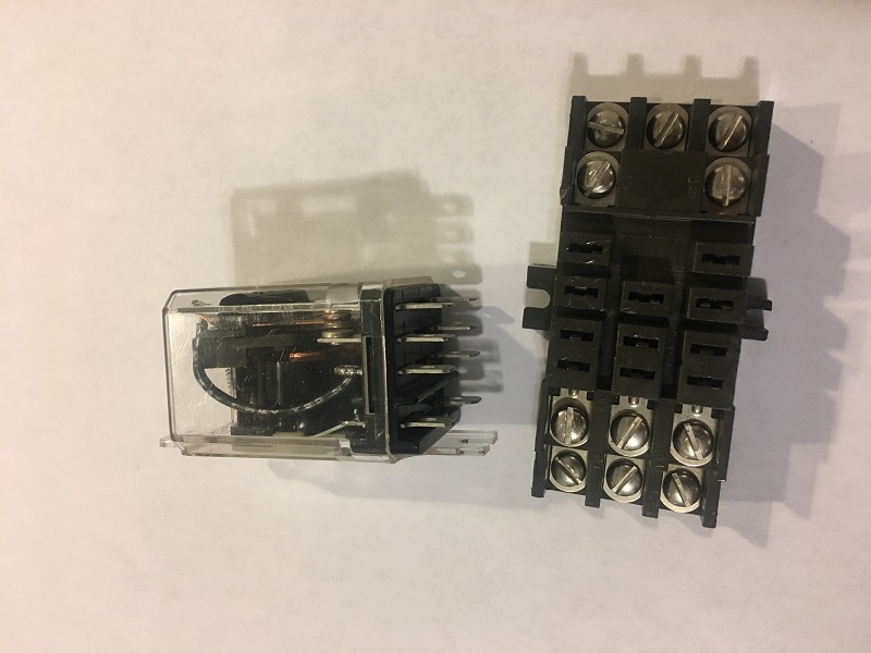
12509-0

This works for the lights on the circuit with just a flicker when it switches back and forth, but those lights are maybe around 200 Watts max and are not an inductive load.  I am thinking that I would like to do the same thing for when the bank voltage is higher and I have excess power for the 110V circuit to use that excess power with my laundry equipment and possibly other loads which may have more inductance.  I have some concerns though because I know that the inductive coils in the motors will store power, and I am thinking that I may have a problem if there is still power from a spinning motor being back fed as it switches the relay on connecting it to my inverter, but I have not done this and am not sure how much of a problem this would be.  My inverter is not connected to my grid, so the power phases will not be synchronized at the time of the switch.  My goal is to not ruin a 20 amp 120V relay or release magic smoke from any other components.  I figure some of you guys probably have experience doing similar switching.  Any thoughts on this?  Rich
A Joule saved is a Joule made!

Mary B

  • Administrator
  • SuperHero Member
  • *****
  • Posts: 3177
Re: A quick question regarding DPDT Relays and inductive loads
« Reply #1 on: December 26, 2019, 03:15:42 PM »
I use a delay when switching inductive loads, 30 seconds is enough to keep from locking a compressor. Bought the delay circuit from eBay...

richhagen

  • Hero Member
  • *****
  • Posts: 1597
  • Country: us
Re: A quick question regarding DPDT Relays and inductive loads
« Reply #2 on: December 27, 2019, 10:31:51 AM »
Thanks, it will complicate things as I will have to use or build a circuit instead of simply using a DPDT relay.  I will need one to delay the switch from the grid to the inverter, and another to put the dead space between the switch from the inverter back to the grid.  Thanks for the response Mary. 
A Joule saved is a Joule made!

Mary B

  • Administrator
  • SuperHero Member
  • *****
  • Posts: 3177
Re: A quick question regarding DPDT Relays and inductive loads
« Reply #3 on: December 27, 2019, 01:38:15 PM »
All you need is what they call a soft start on the relay coil. It delays the coil form reaching cut in voltage. China to the rescue! https://www.ebay.com/itm/AC-110V-220V-0-8W-70s-Delay-Relay-Module-Adjustable-Power-ON-OFF-Delay-Circuit/274166439650?hash=item3fd597dee2:g:UNUAAOSw8GNdu5nM

richhagen

  • Hero Member
  • *****
  • Posts: 1597
  • Country: us
Re: A quick question regarding DPDT Relays and inductive loads
« Reply #4 on: December 27, 2019, 04:56:25 PM »
I can not use the simple DPDT relay that I used for the lighting though as it only disconnects from the grid when it flips from the normally closed to the normally open connections which even if I delay when it flips which is what I gathered from your reply.  I will need to delay the flip back to the grid as well as the flip to the inverter.  I looked over that Chinesium circuit.  It seems like a high part count for what I need done, and I am not confident in that alleged 20 Amp relay as it is a fraction of the size of the ones that I have.  On the other hand it probably has lower coil losses.  I think I will roll my own in that I will build a circuit to charge a capacitor to ramp up the voltage to activate the coil with capacitance across the coil calculated to cause an appropriate delay in both activating the coil and in releasing it once the inverter power has been removed.  I ordered up a couple of 12VDC coil variant for my relay though as I only have 120VAC and 240VAC coil variants in 20 Amp AC on hand at the moment, and they are good to have on hand even if I do not use them for this specific purpose. 
A Joule saved is a Joule made!