Author Topic: Charging a 24v bank from a 48v bank...or vice versa...how to do it? Can it done?  (Read 3479 times)

0 Members and 2 Guests are viewing this topic.

makenzie71

  • Hero Member
  • *****
  • Posts: 549
  • Country: 00
So i have a bunch of different turbines running at 24v and 48v.  I want to simplify my load side...Is there a reasonable way to feed a 200 amp/hr 48v bank into or from a 100 amp/hr 24v bank?

Mary B

  • Administrator
  • SuperHero Member
  • *****
  • Posts: 3175
24 to 48 volt DC/DC converter. No clue if they make one in that voltage range... I use 24 to 12 volt converters to run the ham radio gear...

Scruff

  • Hero Member
  • *****
  • Posts: 698
  • Country: ie
48V -> 24V = easy peasy. MPPT Charge controller with current limiting.

24V -> 48V you can get MPPT boost but really rare, so rare that compatibility takes precedence over performance (Renogy).

You might find a DC-DC charger for this, it's getting popular with liveaboards although I have a problem with the bang for buck aspect of these compared to series alternators.


makenzie71

  • Hero Member
  • *****
  • Posts: 549
  • Country: 00
That thought crossed my mind...the mppt charge controller...i just didn’t know if it’d try to suck my 48v bank dry. 

makenzie71

  • Hero Member
  • *****
  • Posts: 549
  • Country: 00
So that's what I was concerned about...I have an MPPT charge controller that will do a regulated drop down to charge a 24v bank with a 36~70vdc input.  Problem is that it'll be trying to draw my 48v bank all the way down to 36v.

Maybe I can use a dump load controller...open the feed to the other bank up any time voltage gets above 52vdc...or maybe I can try running my Heli at 36v but I don't think it's going to like that...

Scruff

  • Hero Member
  • *****
  • Posts: 698
  • Country: ie
You can play with LVD on the controller maybe to set thresholds or use voltage triggering to disconnect the charge source.
Depends on the batteries too, I usually assume the higher voltage would be bigger so more capable of finding a natural regulation. Eg. if 48V is 200Ah and 24V is 100Ah unlikely the 24V will every drain the 48V to 50%SOC.

Dump controller would work too but I'm not sure if that's healthy to have batteries on both sides.
Whatever it is has to have current limiting.

PWM generally speaking doesn't like a Voc >170% the battery voltage...it often can do it but not for as long as one that isn't asked to.

makenzie71

  • Hero Member
  • *****
  • Posts: 549
  • Country: 00
That's the issue, the bigger bank is going to be the 24v bank...I think.  I haven't decided which way to go yet.  The issue I'm having is I have one 48v turbine, and everything else runs 24v, and the inverters run off the 24v...so it is possible the 24v bank can draw the 48v bank down.  I think it's something so unorthodox that I'm going to have to just try something and see how it works and adjust from there :/

Scruff

  • Hero Member
  • *****
  • Posts: 698
  • Country: ie
Not that unorthodox I was tooling for 48V then I realised HGV was 24V and that'd be a better investment aside from the intrinsic problem of big cables and expansion cost-prohibitive hardware.
Swings and roundabouts. There's more availability of used gear at 24V but less competing buyers at 48V.

It depends on the controller you are using even the (larger) ones without load terminals will often still have LVD that opens the FETs so you could set the 48V to MPPT but only to 50.5V.
MPPT controllers usually have current limiting as standard, PWM usually not.

Scruff

  • Hero Member
  • *****
  • Posts: 698
  • Country: ie
Thuther option is use transformers upstream of the 48V rectifier.

makenzie71

  • Hero Member
  • *****
  • Posts: 549
  • Country: 00
So that actually seems to work...I ran my 48v bank to the PV side of this cheap 60a controller and it's dropping the voltage down to 29vdc and hitting my 24v bank.

https://youtu.be/yUHF3Re622U

makenzie71

  • Hero Member
  • *****
  • Posts: 549
  • Country: 00
As it turns out...it doesn't work, unfortunately.  If the 48v bank votlage is stable it fires up, but if the turbine is fluctuating voltage it goes flat.  I think when the voltage is jumping around the MPPT function is screwing with it...I'm going to have to look for another solution.

Warpspeed

  • Full Member
  • ***
  • Posts: 169
  • Country: au
So i have a bunch of different turbines running at 24v and 48v.  I want to simplify my load side...Is there a reasonable way to feed a 200 amp/hr 48v bank into or from a 100 amp/hr 24v bank?
Yes, a bi directional switching power supply would be pretty simple.
 
It only gets complicated if you require other than a direct fixed voltage relationship between the two batteries. If they are of similar battery chemistry, a fixed voltage relationship will work fine.

The batteries will act as if they were connected in parallel, and charge/discharge together with power flowing either way to keep the two voltages proportionally equal.  A fixed  2:1 voltage relationship requires a fixed duty cycle of 50% on 50% off.   That fixed duty cycle should be easy to generate with a digital  counter.

A simple buck/boost topology with a series choke running constantly at a fixed duty cycle should be all that is required.
It should not require a "smart control system" as such, as the voltage relationship will always be fixed.
« Last Edit: March 17, 2022, 01:10:23 PM by Warpspeed »

Warpspeed

  • Full Member
  • ***
  • Posts: 169
  • Country: au
Ten days, and nobody has shown the slightest bit of curiosity in how to do this ?

So I will not bother going to all the considerable trouble to explain how a very simple bi directional switching power supply could effectively couple together two batteries (of the same battery chemistry) in parallel, but with the batteries having a different numbers of cells in each.

I am REALLY disappointed in you guys.


joestue

  • Hero Member
  • *****
  • Posts: 1763
  • Country: 00
a fixed 50% duty cycle buck converter can be made from the self oscillating half bridge driver irs2153.
My wife says I'm not just a different colored rubik's cube, i am a rubik's knot in a cage.

Warpspeed

  • Full Member
  • ***
  • Posts: 169
  • Country: au
Or a simple oscillator and a flip fop, assuming a 2:1 ratio of the number of cells and battery voltages of course.

That is all you need, no pwm, no voltage measurement, no control loop, no feedback.

If there are an odd numbers of cells in one or both batteries, it can still work with the appropriate fixed duty cycle, but 2:1 is dead easy and would probably cover most peoples needs.

clockmanFRA

  • Hero Member
  • *****
  • Posts: 952
  • Country: fr
    • Renewable Energy creation
I am listening Warpspeed, but i have enough trouble understanding until i would need to activley do it.

But i personally would be very interested, as folk out there have some very strange installations. Yea i try to get them to stick with 48v systems but.......
Everything is possible, just give me time.

OzInverter man. Normandy France.
http://www.bryanhorology.com/renewable-energy-creation.php

3 Hugh P's 3.7m Wind T's (12 years) .. 5kW PV on 3 Trackers, (8 yrs) .. 9kW PV AC coupled to OzInverter MINI Grid, back charging AC Coupling to 48v 1300ah battery

Warpspeed

  • Full Member
  • ***
  • Posts: 169
  • Country: au
My own interest in all this has arisen since I originally went off grid with a 100 volt system using thirty 60Ah Winston lithium cells.
That is only 6Kw hours of storage which just meets my daily needs in mid winter. But if the following day is a zero solar dud day, I and my battery are both in deep trouble the following night.

So I really need more battery capacity that will cover perhaps up to three days of zero sun.
 
I really do not want to buy another thirty Winstons at the current prices of $A1.85 per amp hour.
The Chinese 280Ah cells look a lot better at around $A0.50 per amp hour.  Each cell ends up adding about 1Kwh.
But thirty 280Ah cells and 30Kw of extra storage is far more than I either need or can really afford.

So the grand plan is to order eight of these cells initially (which I have just done) increasing capacity from 6Kwh up to about 14Kwh and see how that goes.  I may later add another four or perhaps another eight more cells as required, but that is in the future.

So what I need is some power electronics with which I can select however many cells I wish to match up to the existing 30 cells.

The trick will be to initially couple eight 280Ah cells up to thirty 60Ah cells in such a way that all 38 cell voltages track using the same BMS and the whole thing behaves like a unified single battery bank.
I have some rather interesting ideas on that which involve the overall voltage matching (24v to 100v nominal) as well as a high power cell balancer that should I hope get all cells to track even though they are vastly out of balance capacity wise.

I discovered an interesting effect when testing one of my many home built mppt solar controllers. Most of these use the standard buck topolgy using a series pass mosfet, a flywheel diode and a choke to reduce the solar voltage down to the battery voltage with some clever pwm software.
14795-0

« Last Edit: April 17, 2022, 06:20:51 AM by Warpspeed »

Warpspeed

  • Full Member
  • ***
  • Posts: 169
  • Country: au
In an attempt to reduce diode losses and reduce heat sink temperature, the flywheel diode was replaced with a synchronous mosfet switch, which was actively driven "on" when the upper mosfet is driven "off".  Note, this is fairly normal practice in many types of switching power supply to increase efficiency, especially at low dc output voltages.

I had all kinds of problems with exploding mosfets, until I realised what was actually happening, and the cause of my problems were absolutely fascinating.

Now I will draw the EXACT same circuit mirror image, its easier and more intuitive to understand that way.
14796-0

« Last Edit: April 17, 2022, 06:23:26 AM by Warpspeed »

Warpspeed

  • Full Member
  • ***
  • Posts: 169
  • Country: au
I did not actually have a solar panel there, only a dc power supply, but if the PWM duty cycle was reduced, increasing the on time of the lower mosfet, the whole circuit operates as a dc boost converter, drawing current from the battery and producing an essentially ever rising dc output voltage until something breaks down.  Usually the upper mosfet.

So the lesson was, active rectifiers work fine driving a resistive load, but if you try driving a battery you might be in trouble if the mppt software reduces the duty cycle far enough.

I never thought this bi directional power feeding effect with a buck regulator could ever be useful for anything at the time, but I have since done more testing and have come up with this rather interesting topology:
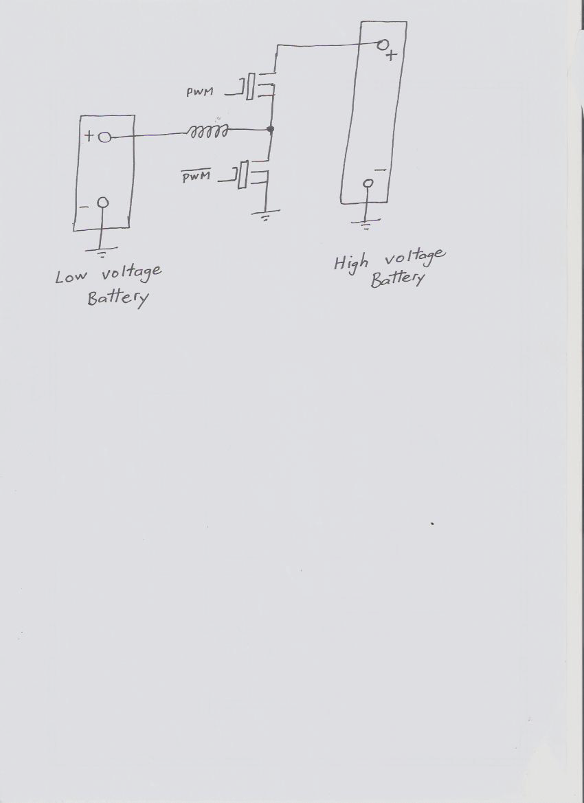
14797-0
The interesting thing is that current can flow either way from one battery to the other, depending on duty cycle and relative battery voltage.
At 100% duty cycle the upper mosfet is always on, the lower mosfet always off, and two equal voltage batteries are solidly in parallel.
At exactly 50% duty cycle one battery can have twice the voltage of the other, and no current will flow except for a small ripple current that flows in and out of both batteries, but there is no net dc current transfer.
If one battery is slightly higher or lower than the 2:1 voltage ratio current will flow either way until the batteries settle at the 2:1 voltage ratio.
You can charge or discharge either, and both batteries will track each other.

Its also possible to have odd ratios of battery cells, it does not have to be 2:1.
As long as the duty cycle reflects the ratio of the number of cells difference in the two batteries, and the voltage ratio, it also works.  So it should be possible to connect say four cells and sixteen cells together for example.
Fixed known exact ratio duty cycles are easily generated either in software or hardware with digital counters.

So it should be pretty easy to implement a circuit to do what the original poster was asking.

Its early days yet.  The cells I have just ordered from China are supposed to take eight weeks to Australia, but the Geopolitical situation with hundreds of cargo ships anchored off China not being able to load or unload does not look good.
I cannot do any actual worthwhile power testing without more cells, but the basic concept of this is already proven.
« Last Edit: April 17, 2022, 06:34:53 AM by Warpspeed »

Warpspeed

  • Full Member
  • ***
  • Posts: 169
  • Country: au
It should theoretically be possible to couple say a 48v battery in a caravan to the 12v battery in the tow vehicle.
The batteries should ideally have the same chemistry, which may be problematic in some applications.

clockmanFRA

  • Hero Member
  • *****
  • Posts: 952
  • Country: fr
    • Renewable Energy creation
In an attempt to reduce diode losses and reduce heat sink temperature, the flywheel diode was replaced with a synchronous mosfet switch, which was actively driven "on" when the upper mosfet is driven "off".  Note, this is fairly normal practice in many types of switching power supply to increase efficiency, especially at low dc output voltages.

I had all kinds of problems with exploding mosfets, until I realised what was actually happening, and the cause of my problems were absolutely fascinating.

Now I will draw the EXACT same circuit of my active rectifier mirror image, its easier and more intuitive to understand that way.
(Attachment Link)

Thanks Warpspeed.
I will follow your build with great interest, and very probably make up the power electronics bit in the near future.
Everything is possible, just give me time.

OzInverter man. Normandy France.
http://www.bryanhorology.com/renewable-energy-creation.php

3 Hugh P's 3.7m Wind T's (12 years) .. 5kW PV on 3 Trackers, (8 yrs) .. 9kW PV AC coupled to OzInverter MINI Grid, back charging AC Coupling to 48v 1300ah battery

Warpspeed

  • Full Member
  • ***
  • Posts: 169
  • Country: au
Always run it with the high voltage battery connected.
If you don't, the stored inductive energy can easily go to thousands of volts when the lower mosfet turns off.
The mosfets will pop for sure.
But if the voltage is clamped by a second higher voltage battery that obviously cannot happen.

Running it without the lower voltage battery will be fine, it will just show the expected lower open circuit voltage, just like any normal voltage dropping buck regulator.
But in boost mode, its a real tiger with the output completely unloaded.

JW

  • Development Manager
  • Super Hero Member Plus
  • *****
  • Posts: 4049
  • Country: us
    • Flashsteam.com
Ah I see in your schematic those look like MOSFET without the circle. Here is what I use for my app very strong electro magnet.

https://www.fieldlines.com/index.php?topic=149546.0

 https://www.youtube.com/watch?v=jZasy9XNbYU

https://www.digikey.com/en/products/detail/nte-electronics,-inc/RS3-1D40-21R/11643998?utm_adgroup=General&utm_source=google&utm_medium=cpc&utm_campaign=Smart%20Shopping_Product_Zombie%20SKUS&utm_term=&utm_content=General&gclid=EAIaIQobChMI7PCKv6Ob9wIVQwnnCh13hQDQEAQYBCABEgIq2PD_BwE

The spec on the MOSFET is
- Input  3.5-32VDC
-Output  100VDC  40A

I OUTPUT in parallel  7 or 9 in ARRAY for output. These respond very well with PWM in parallel on input. For my application I need rapid switching so I use https://www.ebay.com/itm/112055841926?hash=item1a170c7486:g:B5wAAOSwzINbu-C5
I use one on each mosfet output

joestue

  • Hero Member
  • *****
  • Posts: 1763
  • Country: 00
So I agree that a synchronous rectification topology will have a problem with unlimited boost volts, but if you simply keep the MOSFETs on in a fixed duty cycle, the ratio of voltage is the duty cycle. So it's up to you to limit it. basically you have to let the current flow backwards otherwise you do get an infinite voltage. (or in the case of a buck converter, the output voltage will rise to meet the input voltage if the output current is below the critical current) see this chart: https://en.wikipedia.org/wiki/Buck_converter#/media/File:Buck_continuous_discontinuous.svg

There will be slightly higher losses at low loads, but it doesn't require any brains and the circuit is simpler.

You can also have the circuit on a circuit so it only turns on if the voltage ratio on the battery exceeds some value. --which is what this person managed to do
https://www.ebay.com/itm/313538468711
« Last Edit: April 18, 2022, 04:46:43 PM by joestue »
My wife says I'm not just a different colored rubik's cube, i am a rubik's knot in a cage.

Warpspeed

  • Full Member
  • ***
  • Posts: 169
  • Country: au
The current will flow backwards if there is something there to absorb the initial voltage spike.
A battery certainly will do that, and so should a large enough electrolytic.

After all, that is the way all boost and flyback converters work, there absolutely  must be a large output capacitor or it will just  self destruct.

I had problems when originally testing a solar controller (with active rectifier) fed straight from a bench power supply into a battery. I blew up my bench power supply that way, and also many mosfets until I realized what was actually happening.

Another way to do this would be a push pull switching power supply with a push pull active rectifier, the transformer ratio providing the exact required voltage ratio. That uses more parts, and designing or finding a suitable transformer a bit of a hurdle, and its a lot less flexible if you wish to add or remove cells from one side.

The suggested two mosfets and a choke topology is about as simple as it gets.
When the duty cycle and two dc voltages coincide exactly, there is only a very small circulating ripple current dependent on choke impedance.

If the voltages change with respect to the fixed duty cycle, the corrective current flow is only limited by dc resistance in the system. So the batteries behave as if they are connected in parallel even though their voltages are different.

joestue

  • Hero Member
  • *****
  • Posts: 1763
  • Country: 00
So the buck converter needs a capacitor by definition because if the switches are just floating out there on its own with too much inductance present, it doesn't matter what the rest of the details are: you open the switch and the current flows out of the inductor through the other switch. causing the voltage across the switch that was just opened to increase to infinity.


i'm just trying to avoid confusion. you can either use an active rectifier with a duty cycle control, or you can use a fixed duty cycle and the ratio of voltage will be fixed regardless which side is connected to the battery. 

you cannot rely on the battery alone to provide enough capacitance because its inductance is too high.

My wife says I'm not just a different colored rubik's cube, i am a rubik's knot in a cage.

joestue

  • Hero Member
  • *****
  • Posts: 1763
  • Country: 00
duplicate
« Last Edit: April 19, 2022, 05:05:25 PM by joestue »
My wife says I'm not just a different colored rubik's cube, i am a rubik's knot in a cage.

Warpspeed

  • Full Member
  • ***
  • Posts: 169
  • Country: au
Both sides of this circuit need some type of energy storage to work.

A buck converter output choke with one end disconnected cannot do any voltage averaging, what you get out will be a rectangular wave exactly the as created by the two mosfets. A buck down converter MUST have an output capacitor or a battery connected to work.

A boost converter will produce a very high voltage spike, like an ignition coil when the points open. That will easily break down any mosfet, no matter how high its voltage rating.  There absolutely must be a capacitor connected across the output of ANY boost topology that uses the flyback voltage generated by an inductor.

You cannot build just half a circuit with vital components missing and expect it to work.
It will work with either electrolytics or batteries, or both together.


mab

  • Sr. Member
  • ****
  • Posts: 429
  • Country: wales
I would be very interested in a working version of this cct - but am doubtful i understand enough to achieve it: Obviously one would need a current limiting cct - one that works pulse by pulse - whichever way the current's actually flowing - and an inductor that doesn't saturate within that limit.

I've acquired 18 very old submarine cells 992Ah C10, (4th hand - perhaps) and am hoping i can resurrect enough to make a 24v set; currently 9 are working the other 9 have some degree of internal short, but as the sealant around the tops has disintegrated, it may be feasible to lift the plates out and physically un-short them.

But even if i get a 24v set to match my existing 24v AGM, the agm cells rest at about 2.1v whereas the old sub cells are at 2.02v - so they still won't share load and charge evenly.

Of course it may be more sensible to weight the whole lot in in part exchange for a new forklift battery - would be a good opportunity to go 48v.

joestue

  • Hero Member
  • *****
  • Posts: 1763
  • Country: 00
i can build you a circuit if you want. no current limit, 1000 amps worth of mosfets. the inductor will melt instead lol.
My wife says I'm not just a different colored rubik's cube, i am a rubik's knot in a cage.

Warpspeed

  • Full Member
  • ***
  • Posts: 169
  • Country: au
I would be very interested in a working version of this cct - but am doubtful i understand enough to achieve it: Obviously one would need a current limiting cct - one that works pulse by pulse - whichever way the current's actually flowing - and an inductor that doesn't saturate within that limit.
I have so many partly finished projects on the go here right now, I hardly know which to work on next.
In about another week I plan to order a big batch of circuit boards from China to combine postage cost.
All these circuit boards are required for four quite different projects, and this battery linking circuit is one of those.

Also on order right now are eight 280Ah lithium cells that I will need to finally test the whole thing properly under actual real loaded operating conditions, and I don't expect to receive those cells for at least another eight weeks.
Waiting for the slow boat from China is a frustrating business, but there is no way I can really hurry any of this up.

Not absolutely sure that a current limiting circuit will be necessary, but we shall see.  If it does become necessary, it just adds a few extra parts, which would be unfortunate, but not a disaster.

Quite right about the choke being non saturating, and I have had some considerable practical experience designing and testing chokes required for high power pwm inverters. These must be able to handle the quite high surge loads of an inverter, without saturation, so its an important issue to make these inverters truly robust.

I designed and built a high current inductance testing rig that has been successfully duplicated by several other members over at the the Back Shed Forum.  With one of those,  its possible to safely ramp current up to fifty to eighty amps or more repetitively in a test choke, and watch what the core does as far as magnetic saturation goes on an oscilloscope. Great fun and very instructive.

If a certain core (with a particular air gap) begins to saturate at a measured peak current, the ampere turns to get there will then be known. 
Its then easy to work out a suitable tradeoff between inductance and the saturation limit for that particular core, for any number of turns. Several of the guys over at The Back Shed have been duplicating these tests, and we have all learned a very great deal in the process.

So fabricating a suitable non saturating choke for this is not going to be at all difficult.  I already have quite a collection of odd chokes here left over from previous experiments, one of which should be well up to the job.

Bossrox

  • Newbie
  • *
  • Posts: 15
  • Country: us
  • DIY'er 22kw solar, 32kw battery storage
    • DIY Solar... Power, Water Heating, Furnaces & Other Off Grid Wizardry
Yes, I've been using a salvaged tesla 48v powerwall & running it thru a growatt charger to convert it to 24v. Been working great.