Author Topic: Bryan's 4Kw motor Conversion Part 2 The testing  (Read 2418 times)

0 Members and 1 Guest are viewing this topic.

ruddycrazy

  • Hero Member
  • *****
  • Posts: 519
Bryan's 4Kw motor Conversion Part 2 The testing
« on: July 22, 2022, 05:25:28 AM »
G'day Guy's,
                   Well looking around my red gum forest I have found some suitable trees to make a set of blades but the question remains what length is required to get the beast to perform best.

Now doing test runs in my big lathe in 5:1 back gear along with the VFD programmed make make the 2HP 3 phase drive motor think it's a 3-1/2Hp one but when 240 volts is reached and it cutsin the VFD is complaining of over current and I used a 100 amp bridge rectifier and 2off 12 volt truck batteries in series I saw a glimpse of 89 amps on the current meter. So repeated the test four times and on the last test the bridge rectifier  flashed out and let the smoke out.

Now as I do have a 16HP Listeriod it is time to give the beast a run to just what can it make and as the engine speed is 1000 rpm and under load around 900-930 rpm I reckon a 3:1 reduction so around 280 to 330 rpm can be reached. I do have to get a new bridge rectifier and this time I'll go for a 250 amp model and the load will be my 24 volt 735AH Forklift battery which powers my shed and who would think a washing machine motor and a few caps has kept this battery going.

As this was made a long time ago for the newer members I will describe this conversion

At work when I pulled off a motor from a gearbox it was saturated and had shorted out so it was a good candidate for a motor conversion, 4Kw flange mount so all the windings went into my copper drum.

I machined up a new rotor from an old warman pump shaft and as I was skewing the poles 10 degrees I counter bored a seat for each magnet and only broke one magnet and had a sore finger for weeks. Now 22 16x13mm round N50 magnets were used and as each magnet found home when i finished the pole was epoxed in then when all four poles were done I potted the rotor for the final pour and 3 weeks later machind the OD of the rotor leaving a 2mm gap on diameter from the windings.

After doing the one wire test I decided to do three in hand 1mm wire and brought out double delta with the windings, why bother with Star when Delta gives us more of what we want if the generator can handle it.

To insert the rotor I used a chain block on my lifting jib on my tractor where the motor was cased in a G sized warman pump housing on blocks, when it hit home the tractor jumped up and I thought what have I made here.

So it is time to test this project out and honestly as the motor conversions are bullet proof a down wind design where no tail is need is considering.

Cheers Bryan

Bruce S

  • Administrator
  • Super Hero Member Plus
  • *****
  • Posts: 5374
  • Country: us
  • USA
Re: Bryan's 4Kw motor Conversion Part 2 The testing
« Reply #1 on: July 22, 2022, 08:23:33 AM »
I was wondering about how many iron based items were on their way to those mags!

Cheers
Bruce S
A kind word often goes unsaid BUT never goes unheard

bigrockcandymountain

  • Hero Member
  • *****
  • Posts: 659
  • Country: ca
Re: Bryan's 4Kw motor Conversion Part 2 The testing
« Reply #2 on: July 22, 2022, 10:16:40 AM »
I've been waiting 10 years to see more of this conversion.  I'll be watching your test with great interest.

SparWeb

  • Global Moderator
  • Super Hero Member Plus
  • *****
  • Posts: 5452
  • Country: ca
    • Wind Turbine Project Field Notes
Re: Bryan's 4Kw motor Conversion Part 2 The testing
« Reply #3 on: July 22, 2022, 08:06:31 PM »
Quote
So it is time to test this project out and honestly as the motor conversions are bullet proof a down wind design where no tail is need is considering.

With low-TSR blades and a site that doesn't have crazy hurricane winds, I think that's an excellent idea.
No one believes the theory except the one who developed it. Everyone believes the experiment except the one who ran it.
System spec: 135w BP multicrystalline panels, Xantrex C40, DIY 10ft (3m) diameter wind turbine, Tri-Star TS60, 800AH x 24V AGM Battery, Xantrex SW4024
www.sparweb.ca

kitestrings

  • Hero Member
  • *****
  • Posts: 1376
Re: Bryan's 4Kw motor Conversion Part 2 The testing
« Reply #4 on: July 27, 2022, 12:55:39 PM »
I had the opportunity to work on a lot of downwind turbines, AC induction, grid-connected generators, some years back.  There are a few trade-offs I'd say.  They generally require a heavier frame because of the need to cantilever out past the tower, and because they usually use a horizontal mount, it can make slip-ring assemblies a bit more challenging.  They also can get caught in an upwind position occasionally.

ruddycrazy

  • Hero Member
  • *****
  • Posts: 519
Re: Bryan's 4Kw motor Conversion Part 2 The testing
« Reply #5 on: August 02, 2022, 04:28:06 AM »
So with a downwind wind turbine is the motor (in my case) mounted in line with the centre of the tower or offset like when using a tail ?

I still need to source a USB-C cable as I got a new phone and without that cable no pic's can transferred so will get in the coming days so I can put a few pic's up.

Now as the output of the motor conversion is 36mm Diameter I'll be using a conlock and next time I'm down the hill I'll grab one and I'm on making patterns for the pulley setup so will need to get them cast and machined up.

It will some time before I get the cable as inflation is running rampant and my plan is just use some some 400 amp welding cable so 3 runs of that will cost a pretty penny and I'll see how my tax return next goes and by playing it right may just get enough to splash out on the cable.

Cheers Bryan

kitestrings

  • Hero Member
  • *****
  • Posts: 1376
Re: Bryan's 4Kw motor Conversion Part 2 The testing
« Reply #6 on: August 02, 2022, 08:12:25 AM »
Yes, for a downwind turbine the powertrain is in line with the tower axis.  The off-set for an upwind turbine is to present a moment relative to the tower for furling.  For a machine of any size you will need to consider another means of overspeed control, such as power yawing, blade-pitching/feathering, tip-brakes, dynamic or mechanical braking, or in the case of the Proven design a "coning" rotor.

I'm not familiar with the term "conlock", is that the same as a keyway, or a coupling (spline, jaw, Oldham)?  Is there gearing, or a gearbox anticipated?

My preference is upwind, with a tail.  Good luck.

Mary B

  • Administrator
  • SuperHero Member
  • *****
  • Posts: 3175
Re: Bryan's 4Kw motor Conversion Part 2 The testing
« Reply #7 on: August 02, 2022, 11:52:04 AM »
So with a downwind wind turbine is the motor (in my case) mounted in line with the centre of the tower or offset like when using a tail ?

I still need to source a USB-C cable as I got a new phone and without that cable no pic's can transferred so will get in the coming days so I can put a few pic's up.

Now as the output of the motor conversion is 36mm Diameter I'll be using a conlock and next time I'm down the hill I'll grab one and I'm on making patterns for the pulley setup so will need to get them cast and machined up.

It will some time before I get the cable as inflation is running rampant and my plan is just use some some 400 amp welding cable so 3 runs of that will cost a pretty penny and I'll see how my tax return next goes and by playing it right may just get enough to splash out on the cable.

Cheers Bryan

I email my pics to myself. Then move them to a pictures sub folder in my email program. Gives me a backup copy of every picture in case Imgur eats them...

ruddycrazy

  • Hero Member
  • *****
  • Posts: 519
Re: Bryan's 4Kw motor Conversion Part 2 The testing
« Reply #8 on: August 02, 2022, 06:01:53 PM »
Kitestrings a conlock is a parallel lock with 2 opposing internal tapers that tighten to lock the coupling to the shaft. I used one on my first motor conversion with the 3 metre blades and it was still in new condition 7 years later when the blades failed.

Now with a motor conversion they can only supply the max current the copper can handle then the eddy currents come into play and the current tapers off even the rpm is still there so basically they are a bullet proof design.

Now as this project is using a 4Kw motor I reckon the best output I will see will be around 2.5-3 Kw before saturation comes into play.Now after-all as no one to date has done a downwind design with a motor conversion my idea is build this as strong as I can and just see if mother nature can kill it  8)

I do have an 11Kw motor sitting here telling me when is it my turn and my contact for neo's is back on track so that is a later project to get onto, but I do think that one will be powered by a stationary engine as the weight factor is simply too great for what I can do on the farm.

Cheers Bryan
 

kitestrings

  • Hero Member
  • *****
  • Posts: 1376
Re: Bryan's 4Kw motor Conversion Part 2 The testing
« Reply #9 on: August 03, 2022, 09:51:29 AM »
'Conlock', I see now.  We used something called a keyless bushing to attach the stator bracket to the spindle shaft.  It sounds very similar.

My bias, but I would always recommend a means of controlled shut-down from the ground; ideally one that doesn't rely on wiring or electronics.  The problem can be if the rotor becomes imbalanced due to icing, a bearing fails, or if somehow the rotor breaks free of the generator.  A run-away turbine is frightening to witness (I've seen a few) and quite dangerous.  And unfortunately, Mother Nature is patient (time's on her side), but will rise to this challenge.

I don't mean to be a downer, but do be safe.  Good luck with it. ~ks

ruddycrazy

  • Hero Member
  • *****
  • Posts: 519
Re: Bryan's 4Kw motor Conversion Part 2 The testing
« Reply #10 on: August 05, 2022, 05:06:35 AM »
G'Day Guy's,
                   Well finally got that cable so now installing the Gimp so I can resize them so they will come in the next post.

Got thinking about the test and how to get the right speeds for simulating the wind, now as my 16hp Listeriod runs around 900 rpm I thought well a 2:1 reduction can go the lay shaft and at 450 rpm the beast should be in it's prime. I knew i had some step pulleys off old drill press's so dug them out and found one was still connected to the AC rotor shaft duly pulled off the pulley and bearings and decided well as the step pulley end of the shaft is keyed and it is a neat fit to use the rotor shaft. Well it was a bit of fun cutting off the rotor and in the end had to do 2 cuts opposing so I could crack it open to get the shaft out. Sure enough it wasn't going to press out as the shaft had a parallel knurl where the rotor was so the rotor would of been built on the shaft.

As the 2 step pulley are different diameters this does play into my favour  where I worked out the reduction would give me 255 rpm which is just above cutin and in the centre pulleys both are 120mm so that will make 450 rpm. The other one to use is about 740 rpm so that will be I reckon close to saturation point so by using this rpm as the set point that disk brake I'll be putting on can be tuned.

Cheers Bryan

Edit: Trying to upload pic's but on the preview it's just a white box and no pic


ruddycrazy

  • Hero Member
  • *****
  • Posts: 519
Re: Bryan's 4Kw motor Conversion Part 2 The testing
« Reply #11 on: August 05, 2022, 05:27:48 AM »
G'Day Guy's,
                    Well this pic is the planned site where the 2Kw conversion is going which is on top of the hill to the right, walked outside this arvo and just had to take that pic.

14951-0

Ok here is a pic of the conversion and as we can see I did make the output shaft nice and long so the disk brake can be attached

14952-1

Here is a pic of the front of my shed which I took when I was marking out the 6mm plate for the motor mount and the plate, now in the corner is that 16HP engine I will be using for the testing and beside that bench where that 3Kw inverter is sitting which is the one I got custom made in Taiwan back in '05 and when I contacted them about a schematic they said the never made that model. got an email a few days later and it turned out the enignear that I dealt with ended starting his own business making them and made a killing on ebay. That battery beside the table is a 24 volt 735AH forklift battery that has taken on a new life in my shed and just loves this wild weather in winter.

14953-2

More pic's to come when i get that pulley setup on the go and I am thinking of making pattern so I can machine up a variable speed drive so input speed in and variable to the max so for testing out conversions will be a breeze.

Cheers Bryan

14953-3


ruddycrazy

  • Hero Member
  • *****
  • Posts: 519
Re: Bryan's 4Kw motor Conversion Part 2 The testing
« Reply #12 on: August 05, 2022, 06:36:28 AM »
Well why I'm on a "rant" here it goes

As the Beast will serve us a a major power source for a long time it does need a brain so I'm going to drill hole in the rear of the shaft and epoxy in a 3x3mm neo and put in a hall effect sensor so I can measure the rpm of the turbine.

A wind speed meter will be made which can connect well under the blade sweep to get a true reading so data can be collected about wind speed and rpm.

A couple of DS18S20's to monitor the motor temp and the current temp will be put in and a setup so wifi can be used to transmit the data.

Maybe a few guru's on electronics can pipe in for the best option to use and a couple of 5 watt panels attached to the housing can charge the battery that powers the brain.

Now for the disk brake the amount of fluid needed to close needs to be done as I think a decent solieniod I can make can do the job when over speed conditions come into play.

Many years ago I documented this on another forum and I lost all the pic's of the build so if any member can access that thread and tranfer the pic's over it will make my day.

The true test on the 16 HP motor will determine what the thickness of wire is needed for the cable run and I am thinking that pattern can make for a saleable item  where one does need to test RPM of the conversion they made.

As Oztules said this is one bullet proof design from a Ozzie now I do take notice and I hope that Mexican is still walking and you know the old saying anyone south of you in Oz is a Mexican.

Now and when this 4Kw starts to work I do think back about this great bloke that got me line hook and sinker that it won't have a tail to put a name on it

RIP Zubbly the knowledge you gave me and that dream I had about getting that 4Kw in the air was real but in a dream.

Now if I can I add if I ever get to sell one of my motor conversion projects I will with a hand of contacts send 8% of the sell price to the family

"end Rant"

kitestrings

  • Hero Member
  • *****
  • Posts: 1376
Re: Bryan's 4Kw motor Conversion Part 2 The testing
« Reply #13 on: August 05, 2022, 10:05:27 AM »
Nice pics!  I like the 'rainbow's end', and I like that generator.

Some (many) years back I worked on downwind, AC induction wind turbines.  We had a single-phase model that relied on an rpm pick-up/sensor as part of the control scheme.  I believe it was to allow the rotor to free-spin below cut-in and then connect, in synch with the AC main; in theory anyway.  It never worked well.  We just always had a battle getting clean rpm feed to the controller.  I know the cable had to be shielded, grounded, etc.  Others may know more what the obstacles are and how to overcome them.

On our axial we used an rpm sensor designed by Brian Smith, who used to frequent here.  It works off the frequency of one of the AC leads.  Seems to work well.
14954-0

So, you are using a disc brake, but I didn't follow - does/will it have some sort of hydraulic operation to activate it?

Mary B

  • Administrator
  • SuperHero Member
  • *****
  • Posts: 3175
Re: Bryan's 4Kw motor Conversion Part 2 The testing
« Reply #14 on: August 05, 2022, 12:50:45 PM »
Key to using a hall effect sensor is shielded cable that is only grounded at the electronics end of the path. Ground both ends you can set up a ground loop that introduces noise. How my antenna rotors work.

Next step up is use an encoder but they cost 8 times a hall effect sensor! But they are very very accurate. They are an option on the rotors I use and offer .1 degree accuracy and use an absolute encoder that remembers its last position after a power loss.

SparWeb

  • Global Moderator
  • Super Hero Member Plus
  • *****
  • Posts: 5452
  • Country: ca
    • Wind Turbine Project Field Notes
Re: Bryan's 4Kw motor Conversion Part 2 The testing
« Reply #15 on: August 07, 2022, 12:50:54 PM »
My alternative is to skip the encoders and speed sensors altogether and just sense zero-crossing with a microcontroller.
This works better than typical frequency sensing chips because they are confused by noise, and often prefer the noise over the base signal.
Most microcontroller have frequency sensing functions and they are also fooled by noisy AC, so my trick is to use an Interrupt on each zero-crossing.
If you don't mind programming a micro you can use a simple program (20-30 lines of code) to sense the zero-crossing of the AC tapped from the 3-phase lines.

Once I got the baseline program working, I got fancy and added LCD display and some other stuff.  An 8-pin microcontroller worth 5 USD will do if you just want a tachometer.
http://sparweb.ca/tachometer/

14957-0
No one believes the theory except the one who developed it. Everyone believes the experiment except the one who ran it.
System spec: 135w BP multicrystalline panels, Xantrex C40, DIY 10ft (3m) diameter wind turbine, Tri-Star TS60, 800AH x 24V AGM Battery, Xantrex SW4024
www.sparweb.ca

SparWeb

  • Global Moderator
  • Super Hero Member Plus
  • *****
  • Posts: 5452
  • Country: ca
    • Wind Turbine Project Field Notes
Re: Bryan's 4Kw motor Conversion Part 2 The testing
« Reply #16 on: August 07, 2022, 12:58:13 PM »
Footnote:
This circuit will spew out tachometer data to a LCD or your computer serial port twice per revolution of the turbine, meaning the data comes in 5-10 times per second in a strong wind.  So you need to have a LCD that refreshes quickly otherwise it's a blur.  The colorful LCD in the picture above is actually updated every 10th cycle.  Even at that its refreshes are too slow in the winter.  On the other hand, the serial port is fine with any data rate the tachometer can spit out.
No one believes the theory except the one who developed it. Everyone believes the experiment except the one who ran it.
System spec: 135w BP multicrystalline panels, Xantrex C40, DIY 10ft (3m) diameter wind turbine, Tri-Star TS60, 800AH x 24V AGM Battery, Xantrex SW4024
www.sparweb.ca

ruddycrazy

  • Hero Member
  • *****
  • Posts: 519
Re: Bryan's 4Kw motor Conversion Part 2 The testing
« Reply #17 on: August 26, 2022, 03:42:07 AM »
G'Day Guy's,
                    Well it has been awhile since I updated this post so here we go....

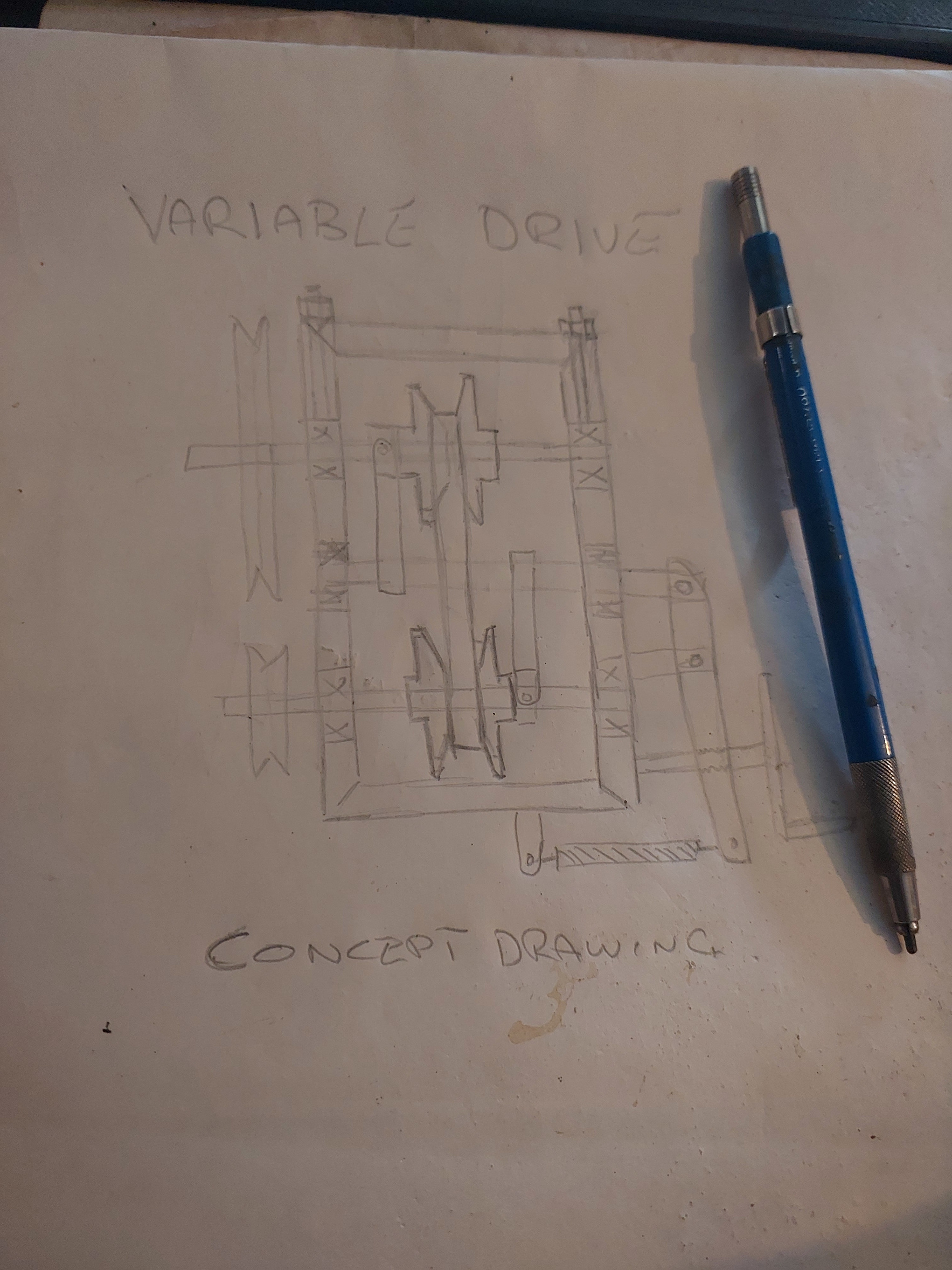
I had a thought on how to regulate the RPM and came up with a concept drawing for a variable drive
14979-0

So as one can see the centre shaft regulates the speed and I have started to make the pattern of the disks so I can get them cast so the normalizing can start after I rough machine the castings.

Started a new job and got told see those packs of 6" pipe well they are offcuts ( insert Shocked emoji) plenty of larger pipe there so the design for the tower is going to come together. I'm thinking with the pipe length being 3 metres of welding 3 sections and welding in bracing on the joints where the above joint can be a section for mounting the guy wires.

So the gin pole will be the same 6" section and same length so I can just use my tractor to raise and lower the tower.

Now for the smarts for this project I will be making a circuit board with a pic32 as the brain and I'll program MMBasic in it so the programming will be done in Basic where talking it out with the girls can figure out the master plan then I can tech the girls just how to write a basic program.

There is still one task to sort out and thats the wire run and my thoughts of using 400 amp welding cable may be a tad over board so my question is for bringing down around 3Kw of wild AC what cable is the best.

Another task to solve is setting up a prony brake when I do the test and I'm thinking as this is a flange mount motor a solid coupling could hold the weight then a prony brake can be setup BUT as I've only read about this method some guidance will be needed as getting all the data is needed to establish the blade length and profile. I am thinking Sparweb is a guru at this and provide some info on doing this practice as this is something I do want to learn, back in the day when I was doing that engineers degree only to find doing shutdowns was the go I didn't get the learning for that theory.

My goal is get this in the air and finished so I can start the next one using a larger donor motor and get the magnets soon before the China bubble bursts.

Cheers Bryan

bigrockcandymountain

  • Hero Member
  • *****
  • Posts: 659
  • Country: ca
Re: Bryan's 4Kw motor Conversion Part 2 The testing
« Reply #18 on: August 26, 2022, 08:46:57 AM »
Hey Bryan, have you thought about using your tractor pto for the variable speed for testing?  A 540rpm can usually be slowed down to about 135 rpm by running the engine around 500rpm.  Of course you could go lower with a couple pulleys.  Maybe I'm understanding wrong.  The variable speed is just for testing right?

Tower sounds like it will end up being exactly like mine.  It was 3 offcuts of 7" piling pipe that i welded together.  They were about 3m each too.

I used 2 awg aluminum wire direct buried for mine.  It seems to work fine.  I don't worry about a little line loss at high power.  The aluminum was about 1/3 the price of copper, so it was an easy decision.  I run higher voltage down and only 2kw so your numbers will be different.

Thats about all i can add.  Cheers from Canada

Derek

SparWeb

  • Global Moderator
  • Super Hero Member Plus
  • *****
  • Posts: 5452
  • Country: ca
    • Wind Turbine Project Field Notes
Re: Bryan's 4Kw motor Conversion Part 2 The testing
« Reply #19 on: August 26, 2022, 07:59:38 PM »
Better go into a continuously variable transmission like that with your eyes open...
https://www.carfax.com/blog/cvt-pros-and-cons
https://youtu.be/a3PF4fPXe9U?t=18
https://upload.wikimedia.org/wikipedia/commons/transcoded/4/41/Claas_Mercator_12_August_2020_JM_%287%29.webm/Claas_Mercator_12_August_2020_JM_%287%29.webm.1080p.vp9.webm
Things you need to make a CVT work: big opposed forces, thick v-belt
Efficiency looks like 75%
To make it work efficiently... extremely tight tolerances, oil-filled gearbox, steel belt or chain

If you're also preparing to bench test the power, well then you can get things figured out that way, make the blades the diameter you need, and just run a direct-drive to get CP about 40-50% efficiency.  The variable transmission will waste about 20% so it would have to boost your prop match to near perfect over a very wide range to be worthwhile.

Controlling something like that from the ground also has its own challenges.  You've got the control circuit on the ground, and the machine up the tower.  Need some skinny wires in between so it invites fidgety things like slip rings.

It would be cool to see, however.
No one believes the theory except the one who developed it. Everyone believes the experiment except the one who ran it.
System spec: 135w BP multicrystalline panels, Xantrex C40, DIY 10ft (3m) diameter wind turbine, Tri-Star TS60, 800AH x 24V AGM Battery, Xantrex SW4024
www.sparweb.ca

SparWeb

  • Global Moderator
  • Super Hero Member Plus
  • *****
  • Posts: 5452
  • Country: ca
    • Wind Turbine Project Field Notes
Re: Bryan's 4Kw motor Conversion Part 2 The testing
« Reply #20 on: August 26, 2022, 08:58:01 PM »
Oh haha <slaps forehead> you must mean making the variable speed tranny FOR testing, not putting a contraption like that up a tower.
A guy named Chris did that once, so I guess I jumped to that conclusion!

Before getting into cable sizing, what's the system voltage you're using?
No one believes the theory except the one who developed it. Everyone believes the experiment except the one who ran it.
System spec: 135w BP multicrystalline panels, Xantrex C40, DIY 10ft (3m) diameter wind turbine, Tri-Star TS60, 800AH x 24V AGM Battery, Xantrex SW4024
www.sparweb.ca

ruddycrazy

  • Hero Member
  • *****
  • Posts: 519
Re: Bryan's 4Kw motor Conversion Part 2 The testing
« Reply #21 on: August 27, 2022, 04:24:03 AM »
Sparweb when we went on the grid back in '03 24 volts was the best so that is what we stuck with, our selectronic inverter is still going aswell as as our 80 amp battery charger. for the last 10 years a 24 volt 600AH forklift battery has provided house power.

So yes this motor conversion was wound for a 24 volt system and when it comes time for a new inverter I will just make my own using the Oztules method as us Aussie's just make things that just plain work.

I mean why change just because the times have and as everything is made in China now the initial cost to upgrade will way out strip the advantage of staying at 24 volts.

I've told the family about going for a drive so I can find my old mate and get some new forklift batteries as my intention is to put several in parallel to get the AH up there.

I scored a 1850's wood stove I'm restoring which has a wet back so I intend either to use the stove or the dump load to heat our hot water so we can stop paying for expensive LPG just for hot water.

I messaged a mate on FB to ask when I can get that pack of 6" pipe could he drive down and pick it up in his 6 wheel car trailer and I offered to pay for the fuel where the response was of course mate and no charge as you have a full trailer to take away for me. So basically my trash is his income and he has said well Bryan you can teach me a lot and it will be a good day.

Now Dereck I just use my tractor for getting firewood and in my front paddock is a spring, now with the rain we have had here it is running again so no way will I use my ol' unbrakeable Hilux to go over there. Besides when I did that tractor swap a few years ago I got burnt where I fixed the problems on his tractor and he stuffed up the PTO on mine, but Karma did come and I won't go into that.

Got a call from my engineer mate who gave me that BHP contract for repairing industrial gearbox's and he has become a life long friend. when I mentioned about a prony brake he went on a rant like nothing where I took him back 30 years.

Now the idea behind this Variable Drive is I can reach the right RPM on that 16HP lister clone and when I use the 5Kw genhead it will be going 1400 rpm to get 240 volts, Now this engine will run off sump oil or vege oil or what ever as it's just a diesel. So just warm up the meduim using diesel then switch over for the run. When it's time to shutdown switch back to diesel to clean out the system for the next startup.

I do have a 1840 bobcat here with a 4cyl Perkins motor and a 32 amp 3 phase Onan genset that is dead as Onan parts are those unotainable parts. So a new trailer will be fabricated so I can have a 32 3 phase and 43 amp single phase genset on wheels that will go the sump oil test. The best part is the hyd pump on this Perkins will give me the crushing power on the rocks on my farm looking for gold.

I have made a 6" jaw crusher and at job I rolled that 1mm screen into a filter but the design was changed so that piece was mine. Also using some 50x6 flat bar rolled some to provide a ring for the drive rollers. This way the output from the jaw crusher will go thru the screen and the smaller gold can be panned off later.

There are 2 faults at the back of my farm and I have been told the gold stram starts in my rear paddock.

With my last job the engineer was Chinese and I got him to get me 2 magnet lifters namely a 300 kg one and a 750 kg one, he texted me they will be here soon as although I don't woirk there anymore he is hapy to come to me and talk about magnets.

Now in my paddock is a 11Kw motor just sitting there just asking to be converted as I have pencilled in some redgum to make 6 metre blades but this will be a few years away as the wood does need to season.

Enough for today and the jourey continues

Cheers Bryan

ruddycrazy

  • Hero Member
  • *****
  • Posts: 519
Re: Bryan's 4Kw motor Conversion Part 2 The testing
« Reply #22 on: August 30, 2022, 05:06:35 AM »
I asked the foreman today about that pipe and he told they were hacked last year and wouldn't pay the ransom so all the stuff out the back isn't on the books so mate take what you want  >:D

So the job on my '95 Hilux this weekend is putting on those riser bars so I can bring home 6 metre lengths. I did measure those pipes today and they are 1709mm diaqmeter with a 5mm wall thickness.

SparWeb

  • Global Moderator
  • Super Hero Member Plus
  • *****
  • Posts: 5452
  • Country: ca
    • Wind Turbine Project Field Notes
Re: Bryan's 4Kw motor Conversion Part 2 The testing
« Reply #23 on: August 31, 2022, 01:13:51 AM »
Great score!
No one believes the theory except the one who developed it. Everyone believes the experiment except the one who ran it.
System spec: 135w BP multicrystalline panels, Xantrex C40, DIY 10ft (3m) diameter wind turbine, Tri-Star TS60, 800AH x 24V AGM Battery, Xantrex SW4024
www.sparweb.ca

bigrockcandymountain

  • Hero Member
  • *****
  • Posts: 659
  • Country: ca
Re: Bryan's 4Kw motor Conversion Part 2 The testing
« Reply #24 on: August 31, 2022, 08:19:04 AM »
Sounds like perfect pipe and a the price is right.  Snap a picture of it on the Hilux.  Should look pretty impressive hauling 6m joints.

ruddycrazy

  • Hero Member
  • *****
  • Posts: 519
Re: Bryan's 4Kw motor Conversion Part 2 The testing
« Reply #25 on: September 01, 2022, 05:10:05 AM »
I made a typo on the diameter the pipe is 170mm diameter with a 5mm wall thickness and the lengths are 4.2 metres long, now as the turbine will be ontop of the hill I will just go 2 sections each for the tower and gin pole. Also a 170mm diameter pipe will be used for the joint and bearing housing for raising/tilting, and i have some pile rio sections a metre diameter and about 1200mm long to use as the foundation. It will be a mammoth job to dig the hole and it will have to be nice and dry to get a concrete truck up the hill as theres no way I will be hand mixing the concrete needed as more than likely a couple of cube's will be needed.

With this new job I will be saving for the wire and I did ask at a scrap yard how much a roll of the thick wire on some of those rolls saying I will be paying cash and was told well mate come on in with some and we can talk a deal.

Cheers Bryan

MattM

  • Hero Member
  • *****
  • Posts: 1176
  • Country: us
Re: Bryan's 4Kw motor Conversion Part 2 The testing
« Reply #26 on: September 01, 2022, 08:05:48 AM »
So around 7" pipe?

I was like, hot damn, 1700mm pipe is sewer grade, but then your thickness was awfully thin.

ruddycrazy

  • Hero Member
  • *****
  • Posts: 519
Re: Bryan's 4Kw motor Conversion Part 2 The testing
« Reply #27 on: September 02, 2022, 04:33:49 AM »
Talking with one of the TA's today about the pipe and he said you better it done while Jon is still here and Jon is the guy that hired me who is retiring in 3 weeks. So this arvo after work had a look for the gal pipe fittings and only found 2 pairs of the 3 way ones in 2 different config's., so they are enough to put the back stay on and I need to measure if I need the front stay on but I do think just the back stay and the head board on the tray will be enough.

I am going to get 5 of the 4.2 metre lengths so I have the option of going higher and enough to do the bearing hub pivot point, I have a couple of 25mm 200 mm disks here so welding them onto the pivot pipe with 2 off plumber block bearings will provide a smooth pivot joint.

I do need to make up some trestles and I'll use some heavy angle iron and drill and counter sink some holes to fit the big ball bearings I have so the pipe can rotate when I weld it. Just grease up the ball bearings and it does provide a cheap rotating device, then I'll use my laser to line the pipe by adjusting each trestle.

I am thinking of welding it up on site so no moving is required and getting it all to stand up is one problem that needs a solution and I'm sure to get a hand off my neighbour and his 2 workers.

So the planning goes on

Cheers Bryan

SparWeb

  • Global Moderator
  • Super Hero Member Plus
  • *****
  • Posts: 5452
  • Country: ca
    • Wind Turbine Project Field Notes
Re: Bryan's 4Kw motor Conversion Part 2 The testing
« Reply #28 on: September 07, 2022, 08:43:09 PM »
Doesn't mean moving the welding rig instead of moving the pipe?
No one believes the theory except the one who developed it. Everyone believes the experiment except the one who ran it.
System spec: 135w BP multicrystalline panels, Xantrex C40, DIY 10ft (3m) diameter wind turbine, Tri-Star TS60, 800AH x 24V AGM Battery, Xantrex SW4024
www.sparweb.ca