Author Topic: new axial design multirotor  (Read 5103 times)

0 Members and 1 Guest are viewing this topic.

JW

  • Development Manager
  • Super Hero Member Plus
  • *****
  • Posts: 4049
  • Country: us
    • Flashsteam.com
Re: new axial design multirotor
« Reply #99 on: January 31, 2023, 07:27:59 AM »
[quote @=Adriaan Kragten]When you are making an entry please specify who your commenting too.[/quote]

MagnetJuice

  • Hero Member
  • *****
  • Posts: 558
  • Country: ca
Re: new axial design multirotor
« Reply #100 on: January 31, 2023, 01:34:15 PM »
Adriaan,

On Reply #64 of this thread, I was explaining how to measure the voltage from a single coil and the steps to take to use the results obtained to find the total peak ac voltage from a 3-phase alternator. Then, convert the results to DC volts.

Then, I gave an example and the the result came to 13.63 DC volts. That was the voltage coming out of the alternator in the example.

Then I said, "To charge the 12-volt battery, you need at least 14.8 DC volts"

14.8 DC volts is the voltage going from the windmill into the charge controller. The implication was that you need at least 14.8 DC volts into the charge controller to charge a 12-volt battery.

Most people knew what I meant. Except you evidently.

On Reply #88 you said:

"I was reacting on the statement that a 12 V battery "must" be charged at a voltage of 14.8 V"
I never said that.

Now I post a quote from Dr. Gary L. Johnson, a retired respected consultant and promoter of wind power and you accuse me of promoting Savonius rotors.

About 3 years ago, I posted this on this Forum:

"There is a lot of cynicism today about VAWT's, but I believe it is because of the aggressive marketing tactics, lies and exaggerated power ratings of the majority of manufacturers of Vertical turbines. The cynicism is not directed at the Vertical turbine itself. I think the majority of the users in this website don't care what device people use to produce energy. Some people use Horizontal turbines, some use Verticals, some use a water wheel or a generator mounted on a bicycle. There was a guy that built a small alternator that was gerbil powered. That was Dan Fink, I'm sure most people here know who he is.

I always encourage people to build something, start learning, and generate a little power."


I don't promote any particular power generating system. I only encourage and try to be helpful to people that are building something to generate power in any way that they can.

I don't write reports. However, if I did write reports, I would not promote them in every post that I write.

leviatan, the OP, appears to have the knowledge, desire and the means to build something to generate power. If I can help him out with something, I will do that.

However, I don't want to participate in filling this thread with irrelevant information.

Therefore, I will not respond to other accusations and misrepresentations.

Ed
What can I do TODAY that would make TOMORROW a better world?

leviatan

  • Newbie
  • *
  • Posts: 46
  • Country: uy
Re: new axial design multirotor
« Reply #101 on: January 31, 2023, 02:07:30 PM »
The thread is diversifying a lot, but everything is interesting and contributes to the discussion from my point of view.

But I leave you some practical considerations.


639 grams each aluminum E x 16 pieces for a complete rotor = 10.224 kg
One disc of Steel of 53cm diammeter x 5mm tick (with a central  hole of 60mm)= 8,574 kg x 4 discs= 34.296 kg.


I have 3.5 times more weights using the traditional way of assembling the generators, and that without being sure that with 5mm thick steel discs they could withstand the attraction of the magnets without deformation in that diammeter (should i guess).

15201-0

Another important point, if you use the magnets in the traditional way (with the widest side magnetized) you need to make sure that the magnet do not touch the same coil on both legs. Achieving that requires the coils to be very thin in their leg width, and to use several layers of coils to cover more stator area.

15202-1

i dont know if that is the real aspect of the stator asembled, but should be very close to that.
In that case apear to have only two layers of coils.
I suspect that as power increases, in addition to increasing the diameter, they have to increase the winding density (at least from photos I saw of real commercial-type stators)

In the case of my design, by being able to refine the area of ​​the magnet but increasing the flux (since the magnets are much taller than they are wide), I can increase the width of the coil legs, covering almost the entire surface of the stator, with two layers of coils.

15203-2

The only "disadvantage" that I see in my design is that the magnets of the internal rotors are not going to have a ferrous metal base disc, but that magnetic flux that in standard designs simply runs a circuit through the rotor disc, here it goes to move to the opposite side of the next magnet.

So although the magnetic flux of one of the magnet faces does not increase, it is not wasted either as it happens in the classic models of Axial PMG.

So I'm going to have two rotors with a metal base (just a ring to hold the whole and that could close the circuit, I'm not too sure about that either, because the distance is large betwen magnets) and two internal rotors that won't have any kind of metal base.

The only way to lighten the weight in a standard design is to open the disc as in the photo
similar to your idea magnet juice.
But that can also cause weakening of the discs if an exaggerated thickness is not used (the disc in the photo must be at least 10mm thick)

So I only see advantages in my design, and my only doubt is if the height that I am choosing for the magnets is exaggerated and I will be paying more money for the magnets without need. But it is something that I can try when the samples arrive, I cut a magnet in half (with what would be 100x20x10mm) and I would test if what the coil generates is still almost the same current or not.

In the tests, when I went from 16mm to 21mm of space between the magnets, the voltage difference was barely 1 tenth of a volt (10%). Perhaps by reducing the height of the magnets (for example from 40mm to 30mm or to 20mm) the magnetic flux can be maintained even at saturation levels.

I can accept that the design may be very confusing to you at first glance, and I really don't have the will to make wooden parts to better illustrate the arrangement of the magnets and how the E's would be assembled in the stator.

But it is likely that you will ask the manufacturer to cut a ring of wood or some other inexpensive material and put the 16 E's inside so that you can better visualize how to assemble the rotor.

For the magnet factory i need to wait until the 6 of february to  advance  because appear theys took one more week of leave.


« Last Edit: January 31, 2023, 03:44:49 PM by leviatan »

MattM

  • Hero Member
  • *****
  • Posts: 1178
  • Country: us
Re: new axial design multirotor
« Reply #102 on: February 01, 2023, 07:24:09 AM »
Lev-

When you assemble everything together, if there is a defect somewhere, do you have to completely disassemble to fix a stator issue?

leviatan

  • Newbie
  • *
  • Posts: 46
  • Country: uy
Re: new axial design multirotor
« Reply #103 on: February 01, 2023, 12:54:05 PM »
in fact you could just move the E's from their base ring shims, and make enough room to settle the issue on the stator. That would mean unscrewing the sheet metal casing of the assembly, but if the entire stator had to be removed due to a critical defect, it would be necessary to remove the 16 pieces and disassemble the entire assembly. Likewise, in the axial ones with discs you have to separate the discs axially to be able to work with the stator, which is almost as complicated due to the force that these magnets exert (I see that they use threaded rods to position the discs safely, at least in the most popular videos).

In my case I don't think there could be a break due to overheating given the size of the generator and the little power that the turbine will be able to deliver. And for the rectifier connections, I am going to put them outside the generator cover in a box isolated from the atmospheric elements, to be able to "play" with the connections between the stators, without having to disassemble anything deeper.

15208-0

PD: just now i found some ways to better manage the extrusion tool of corel draw and i can get to make some drawing with 3 d look.


MagnetJuice

  • Hero Member
  • *****
  • Posts: 558
  • Country: ca
Re: new axial design multirotor
« Reply #104 on: February 01, 2023, 04:36:53 PM »
If you decide to go with the Axial Flux PMG, this is how you could mount it to the turbine.

You will have to figure out where and how to place the bearings.

What would you estimate the turbine RPM to be?

I’m thinking somewhere between 40 and 80 RPM.

I should have all the calculations done by this evening; I have been busier than a 2 pe@uer billy goat.  :D

Ed
« Last Edit: February 01, 2023, 07:19:07 PM by MagnetJuice »
What can I do TODAY that would make TOMORROW a better world?

leviatan

  • Newbie
  • *
  • Posts: 46
  • Country: uy
Re: new axial design multirotor
« Reply #105 on: February 01, 2023, 09:21:06 PM »
The primary idea would be to place it on top of the turbine, so I'm very concerned that the weight doesn't go too high. Weight control is not just a whim. Because when I lift the column (which during the assembly will be horizontal a few meters from the ground) the lever that can make an excessive weight on the tip can complicate the tasks of lifting the column.

But if I can't get the correct rpm in the generator for the power of the turbine (for that I want to play with 6 rectifiers, 2 per stator) I'm going to be forced to place it below and adapt a transmission with helical nylon gears, until achieve the most suitable transmission for the power of the turbine at the desired wind speed.

Today i tested the prototype with the comercial 48v-800w PMG, i used a planetary gearbox 5-1 to give the increase in rpm to the PMG. Those multipliers are delicate and inefficient, but it's easy to swap one for the other and try different ratios, so I chose them for testing.

I really didn't feel like taking the turbine to the coast, it's 300 meters and it's summer here and a spa, it's full of people on the boulevard and many of them stop to ask you what you're testing, and they run the risk of have an accident with so much traffic.

So I went to a couple of squares that face my house, where there are hardly any trees within a radius of 80 meters, and I hoped to find at least some of the wind that I know was on the coast today.

In the end the wind speed was quite disappointing, 4 to 8 k/h and very short gusts (1 or 2 seconds long) from 10 to 14 k/h.

But at least I was able to verify that this relation of transmission does not correspond to the turbine, because it never stopped turning even when the wind dropped to 2 or 3 kph under load.
That gave me the reference that you need a slightly higher transmission, perhaps 8 turns to 1 to force the generator a little more to deliver current in very light winds (it barely delivered 7 or 8 watts at the current speed) and only 40v without load.

I remember trying that same generator but with a self-starting crown gear drive, and a ratio of 15 to 1, and it was too high, it barely allowed the turbine to turn with load, and without load it would pick up 140 volts with a wind of 14 km/h.

So the ideal point for that turbine size must be around 8 to 1, and I don't have planetary transmissions in that range, I have 5 to 1, 13 to 1 and 18 to 1. And those last two are extremely inefficient due to the cascade of gears to reach those multiplications.

That is why I think it will be quite a challenge for the turbine to reach the best rpm ratio with respect to the different torques that it can regulate (they are modest but the differences in torque are noticeable between one type of connection and the other) by changing the connections between stators from parallel to series.

I don't think it will pick up more than 35-40 rpms in the target wind of about 16-18k/h. So I think that the coils could not have wire larger than 1mm to ensure that I will have some resistance to cutting at those VERY low rpms.

And in the event that it does not reach the necessary rpms to obtain useful current, I am going to be forced to use a gearbox, so all the investment in achieving a PMG for very low rpms will be a bit meaningless, but if not you try you will never know.

I made a very basic drawing in corel draw simulating a 3d view of the way the E would be placed on the stators and the steel disc that would hold them, it can help those who are interested in the thread but do not understand how to use it the E to assemble the rotor.
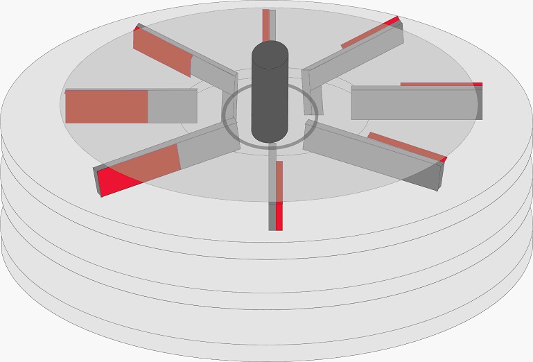
15211-0

The draw have only 8 poles, i dont had will to draw the complete 16 without a easy program to do that.

https://youtube.com/shorts/rOSm4ZdeydU?feature=share

short video of the test today in the afternoon, without load. With load at that low wind speed it barely reached 7 or 8 watts at 10v, which was the connection voltage of the leds.

I am going to order a planetary transmission from 8 to 1 to see if it improves the load a bit, because it would be more than 50% more rpm than the generator would be subjected to with the same torque, because I don't need it to rotate with winds of 3 k/h without generating almost nothing, it is attractive to see it rotate in such a light breeze, but when it takes a real wind of about 20K/h, the turbine will surely speed up a lot and not deliver all its energy to the PMG axis.


« Last Edit: February 01, 2023, 09:34:47 PM by leviatan »

Adriaan Kragten

  • Hero Member
  • *****
  • Posts: 1158
  • Country: nl
Re: new axial design multirotor
« Reply #106 on: February 02, 2023, 01:45:21 AM »
Adriaan,

"I was reacting on the statement that a 12 V battery "must" be charged at a voltage of 14.8 V"
I never said that.

Ed

I went back to your post to see what you have really said and you said "you need at least 14.8 DC volts". This is even worse than a maximum charging voltage of 14.8 V because at least 14.8 V means that you should never use a charging voltage lower than 14.8 V. You don't give good arguments for a charging voltage above 14.8 V but I think that I have given enough good arguments for a maximum charging voltage of 13.8 V.

MagnetJuice

  • Hero Member
  • *****
  • Posts: 558
  • Country: ca
Re: new axial design multirotor
« Reply #107 on: February 02, 2023, 01:51:55 AM »
OK Adriaan, you win.  :D

I'll let you have the last word. This was kicked around a little too long. We can go back to have fun now.

Ed
What can I do TODAY that would make TOMORROW a better world?

MagnetJuice

  • Hero Member
  • *****
  • Posts: 558
  • Country: ca
Re: new axial design multirotor
« Reply #108 on: February 02, 2023, 01:57:29 AM »
30 to 40 RPM??? ay caramba!!!

That's going to be a challenge. I have never designed for anything that low but is doable.

I did some quick calculations for 30 RPM, and you will need about 30 coils in the stator.

The rotor will have 20 magnets, but I will have to use smaller magnets. The 2 x 1 magnets would have been too powerful and you would had to use 2mm wire for the coils.

With the smaller magnets, you would be limited to about 350 watts with 1 magnet rotor and 1 empty steel disk on the other side. If you use 2 rotors with magnets, you could get about 500 watts and use 1.4mm wire. The size of the rotors would be about 19 inches in diameter.

However, you have to go with 12-volts; otherwise, your coils are going to be too big and fat.

Will you be satisfied with that? If you want more power, you will have to use larger diameter rotors and go 24-volts.

I'll search for a suitable standard size magnet that I can use for the calculations.

Ed
What can I do TODAY that would make TOMORROW a better world?

JW

  • Development Manager
  • Super Hero Member Plus
  • *****
  • Posts: 4049
  • Country: us
    • Flashsteam.com
Re: new axial design multirotor
« Reply #109 on: February 02, 2023, 02:46:46 AM »
I have been thinking about something on the larger number of coils being proposed lately. Doesn't that mean more diode junctions between coils or are they 3ph or something like that.

MattM

  • Hero Member
  • *****
  • Posts: 1178
  • Country: us
Re: new axial design multirotor
« Reply #110 on: February 02, 2023, 06:46:13 AM »
I believe he is going 5 rows of magnets and 4 stators.  Each finger of each E plate is a magnet holder.  The stators will sit perpindicular to the E plates, in the area between the fingers.

leviatan

  • Newbie
  • *
  • Posts: 46
  • Country: uy
Re: new axial design multirotor
« Reply #111 on: February 02, 2023, 10:03:02 AM »
I believe he is going 5 rows of magnets and 4 stators.  Each finger of each E plate is a magnet holder.  The stators will sit perpindicular to the E plates, in the area between the fingers.
near  of that, 3 stators, 4 rows of magnets.
24 coils by each stator ( two layers of 12 coils by stator) 72 coils in total.
1mm wire
About the voltage i need to see what happen with all that, i guess 24 or 48v not is a bad option, with only 12 i would need a so ticker wire to hold inclusive low currents.

My calculation of possible rpms is based on the tests I do with the 1/2 scale prototype. If I see that under load conditions delivering about 50-80 watts it rotates at about 70-80 rpms (I should measure it with the tachometer, maybe it is less) it means that if I double the diameter of the turbine, with the same wind speed it moves a perimeter almost twice as large, so the speed of rotation would be reduced by half. And that would mean going from 70-80 to 35-40rpms.


I have seen true axial pmg monsters with rotors of 1.20 meters and more and they feed a 100 watt lamp at 220v, with a relatively smooth spin. But I don't see that they were wonderful either and their weight due to those diameters takes them to levels that a small forklift is needed to move them.

That is why I ruled out from the beginning the path of increasing the size of the rotor to be able to add more coils, because to accommodate the number of coils that I think I need to work at such low revolutions, it would be a rotor of 1.3-1.5 meters in diameter.

https://www.youtube.com/watch?v=cB9ci7Xwreg
Apparently these Chinese guys came up with a 10kw 70 RPM one. I very much doubt that with that size it will generate 10kw at those rpm, but something is apparently generating.

https://www.youtube.com/watch?v=cYtUcyUzrZY  this one are generating but at no less of 60-80 rpm, when rpms down a bit the current disapear.

And there are other much more extreme examples out there on you tube (but since there are thousands of videos it is difficult to find the most remarkable ones without doing a search for hours) but they all tend to the same (at least the homemade ones) they lower the rpm a bit and they do not generate anything.

That's why I think the key is going through many coils of "fine" wire to get many turns and some current at very low cutting speeds. Three-phase connection of each layer of coils, and that the sum of voltages or ampers is made from the rectifiers to avoid that the thin cables (1mm) suffer a lot of overheating. With this it would achieve that the maximum current flow is the one that can be generated by 4 coils together (each phase) and once they go out to their rectifier they begin to add to the current and volts of the other phases and the other stators, but without having to make the circuit for the rest of the windings of the generator.

It is as if we added the current of 6 separate stators of 12 coils with three-phase connection. If each stator generates for example 50 watts, in the end you have 300 watts.

And according to what I calculate that would mean that each series of 4 coils should support about 16 watts, 16 watts for a 1mm thick cable would be very far from heating up. I know because I dedicate myself to design and assembling tactical flashlights for 14 years, and the cables that are used (in short distances of course) are barely 0.1mm thick (and sometimes less) and perfectly handle currents of 25-30 watts without, to date, have seen any burn or lose their insulation under use conditions.

The electrical installations of homes also (220v are used here) use cables of just 1mm to feed everything that is lighting in long distances, and you can suddenly have consumptions of 150-300 watts on a 1mm line many meters long distances and the cables do not overheat either. And there you are circulating almost 1A and more through the cable for hours and hours. Although the installation cable is multicore, which improves the circulation of the current a bit, it is still the same copper.

Lastly I measured the amperage flowing through the test coil (I had to use the rectifier controller for it because although the tester gave me an option to measure A in alternating current, somehow it didn't work) and I only measured about 0.06A at 84rpms (that means around 60 rpms with the real diameter of the rotor) then 4 coils adding his currents by phase is 0.24A. But when I could measure the generation with a complete rotor, with all 16 poles instead of just 2, that current could probably climb up to 4 or 5  times.
So if you could be touching the resistance limit of the insulation of a 0.7mm cable. But until I can test a rotor with at least 8 poles, I can't know what the real generation regime of that coil is. I believe, without having empirical confirmation yet, that 1 mm thick is going to be the right wire to make the coils.

All these calculations collapse if one uses a horizontal turbine, where the improvement in efficiency and the difference in TSR of up to 8 times means that small changes in wind speed could greatly vary the rpm at which the generator rotates, and cause a large difference in current generated by the PMG.

They are very different things and they behave very differently in the face of the wind, so trying to use the same calculation formulas that are used for a horizontal turbine when calculating the generator is a mistake, because the speed of revolutions has nothing to do with it see, between one type and another of turbine.


Mary B

  • Administrator
  • SuperHero Member
  • *****
  • Posts: 3177
Re: new axial design multirotor
« Reply #112 on: February 02, 2023, 01:23:48 PM »
in fact you could just move the E's from their base ring shims, and make enough room to settle the issue on the stator. That would mean unscrewing the sheet metal casing of the assembly, but if the entire stator had to be removed due to a critical defect, it would be necessary to remove the 16 pieces and disassemble the entire assembly. Likewise, in the axial ones with discs you have to separate the discs axially to be able to work with the stator, which is almost as complicated due to the force that these magnets exert (I see that they use threaded rods to position the discs safely, at least in the most popular videos).

In my case I don't think there could be a break due to overheating given the size of the generator and the little power that the turbine will be able to deliver. And for the rectifier connections, I am going to put them outside the generator cover in a box isolated from the atmospheric elements, to be able to "play" with the connections between the stators, without having to disassemble anything deeper.

(Attachment Link)

PD: just now i found some ways to better manage the extrusion tool of corel draw and i can get to make some drawing with 3 d look.

Make sure that external box has a weep hole for condensation and check it yearly to make sure it is open. I have poured water out of tower mounted boxes I ignored for 2-3 years, well sealed NEMA boxes! 2 small weep holes at the lowest edge are the norm.

kitestrings

  • Hero Member
  • *****
  • Posts: 1376
Re: new axial design multirotor
« Reply #113 on: February 03, 2023, 08:00:07 AM »
leviatan,

You might find this site useful:

https://batteryuniversity.com/article/bu-403-charging-lead-acid

Looks like you're otherwise getting some good input on VAWT and alternator design, and hopefully having fun.  Good luck, ~ks

bigrockcandymountain

  • Hero Member
  • *****
  • Posts: 659
  • Country: ca
Re: new axial design multirotor
« Reply #114 on: February 03, 2023, 09:02:36 AM »
Fwiw, 14.8v is right on for L16 size batteries.  I have tried lower absorb voltages, but i always seem to lose capacity, likely from sulfation if i do. 

Mine are set on 15v right now.  (60v because I have 48v)

The book says something like 14.8v as well.  Surette Rolls S550

Midnite brat controllers come from the factory with an L16 setting built in that is 14.6v or 14.8v. 

If you want to equalize with your turbine, you'll need more than 16v.

Sorry about beating this dead horse, it just seemed like the conclusion that was arrived at wasn't correct. 

I'm following this build thread of yours because it is something different that hasn't been done.  I wish you luck with it. 

leviatan

  • Newbie
  • *
  • Posts: 46
  • Country: uy
Re: new axial design multirotor
« Reply #115 on: February 03, 2023, 07:51:15 PM »
Today I took the turbine back to the plaza. The wind did not accompany me again but at least I got gusts of up to 13-14k/h, the average was 4-9 k/h.
Those short 2-3 second bursts at least allowed me to gauge no-load rpm.

The results: barely 38 RPM....Assuming that the wind had at least 20k/h (40% more speed) the scale model could reach at most 53 rpms....

If we take that to double the diameter, surely for a mathematical issue the rpm should drop by half, with sustained winds of 20k/h. That's just too few rpms, barely 25 for the full scale model.
Not enough to move with a minimal speed any generator.
No matter how well achieved the system or the number of coils is exaggerated.

Pretty disappointing. So yes or yes, I'm going to have to do some transmission at least 3 to 1 or 5 to 1 at least.
This changes my idea of ​​design quite a bit, and mounting it on the roof of the turbine depending on a transmission is also much more complicated.
Not an impossible task, but it doesn't pay the effort.

 So there should be a transmission crown mounted on bearings at the base of the turbine. It's not pretty and it's not very practical, the only advantage is that it's a few meters less cable and you don't have to lower the turbine to do some kind of maintenance on the alternator.

But at least having a large prototype allows me to see some problems that if I used much smaller scale prototypes, I wouldn't realize they are hidden there.

In fact if you watch the turbine spin at just 38rpm, having three blades causes a major optical illusion and it seems to spin much faster, but the digital tachometer doesn't lie...


JW

  • Development Manager
  • Super Hero Member Plus
  • *****
  • Posts: 4049
  • Country: us
    • Flashsteam.com
Re: new axial design multirotor
« Reply #116 on: February 03, 2023, 09:20:23 PM »
Quote from: leviatan
If we take that to double the diameter, surely for a mathematical issue the rpm should drop by half, with sustained winds of 20k/h. That's just too few rpms, barely 25 for the full scale model.
Not enough to move with a minimal speed any generator.
No matter how well achieved the system or the number of coils is exaggerated.

For some reason this makes me think of a gear reduction. I always wondered Why ChrisO was so into the gearbox.

In a really good mood tonight :0

"No matter how well achieved the system or the number of coils is exaggerated."

This is because Ohms law helps us to understand why, generally the electro conduction property of the alloy determines its resistance at a given operating temperature.

JW
« Last Edit: February 03, 2023, 09:47:17 PM by JW »

MattM

  • Hero Member
  • *****
  • Posts: 1178
  • Country: us
Re: new axial design multirotor
« Reply #117 on: February 04, 2023, 08:05:02 AM »
If your target was 3 meters across then even that half-sized prototype has was more than enough power to make it interesting if you have a good enough gear ratio.

leviatan

  • Newbie
  • *
  • Posts: 46
  • Country: uy
Re: new axial design multirotor
« Reply #118 on: February 04, 2023, 10:14:14 AM »
The size is not very large neither of the prototype nor of the other. At least not if we start using formulas.
1.7x2.2meters=3.74m2. It is like the same area of ​​a hawt of 2.1 meters of diameter. It's little.

And the big one would be (if it were a hawt) just a rotor with 2.2 meter blades (4.4 diameter of the rotor).
Having in acount a savonius can to obtain only a 60% of the posible production of a hatw of that diammeter, the production would be very modest in both cases.  I measured 80watts at 20K/h with hoverboards motors like alternator, i dont expect so much improvements than that, around 20 watts by square meter.

But the important thing would be that it would work and give power in very light winds, in very strong winds, in gusty winds, basically ALL the time, and the maintenance and security systems would not need to be as sophisticated as in a hawt.

And another bonus would be that they are nice to watch them spin, and they don't make ANY annoying noise or hum.

You exchange efficiency and production costs for the disappearance of annoying sounds, aesthetic improvement and low maintenance.

But let no one imagine here that this is the search to improve efficiency at the level of a hawt. It is simply the implementation of a savonius that does generate something at least. If anyone knows of any commercial-type savonius that has videos that show more production than that (20w per square meter on a normal day), it would be good if they shared it to see what design solutions they found to improve that performance.

At least I, in all these years, could not find any efficiency demonstration video from any company that manufactures Savonius, at most power curves that were not certified by anyone.
They all present their products and talk about how innovative their designs are, but no one puts a tester on it at the time of the video...and we all know that without load, everything spins very fast. :)

https://youtube.com/shorts/9zwc2h408Dc?feature=share


« Last Edit: February 05, 2023, 09:08:45 AM by leviatan »

MagnetJuice

  • Hero Member
  • *****
  • Posts: 558
  • Country: ca
Re: new axial design multirotor
« Reply #119 on: February 05, 2023, 09:50:39 PM »
I saw on youtube where you said that you want to build 10 or 15 generators.

Are you planning to sell these?

I think that a direct drive axial generator for the big turbine is going to be heavier that what you want. Because I checked and that turbine is going to be rotating about 25 RPM with 25 k/h winds.

You are going to have to go with gears. If you go with 8 to 1 gear ratio, the generator will cost a lot less. It will also be a lot easier to install and if you need to service it, it will be easy to remove.

I was working on one like this one, it would have an output of about 500 watts at 35 RPM. It has a diameter of 26 inches. One for 20 RPM it would be too big and heavy. This one has 20 magnets and 30 coils.

15225-0

Ed
What can I do TODAY that would make TOMORROW a better world?

leviatan

  • Newbie
  • *
  • Posts: 46
  • Country: uy
Re: new axial design multirotor
« Reply #120 on: February 06, 2023, 08:57:23 PM »
The issue with the size of the generator, as I see it, is that if I go to a size related to the power of the turbine, I could buy one equal to the one I use for the prototype, 800 watts and 48v. Or something just more powerful.

But since it requires a very high transmission, I will lose a lot in the conversion. And another thing that keeps me from going by the easiest and most economical way, is that the day there is a storm with winds of, for example, 40-60k/h, a small generator with a transmission of 8 or 10 to 1 probably it's done cooking.
I understand that a disc brake can be installed, but... I wouldn't want to lose generating power in those stormy winds (pulling straight to the grid of course, no battery bank would be suitable for that).

They would probably be the only days that I could feel really proud of the production.

So according to the power table I have (I don't know if it's exact, but I take it as such in the absence of other sources).

in a wind of 5m/s (18 k/h) I have available 76.5 watts in the air per cubic meter.
For an area of ​​15 square meters (which would be the swept area) 1147 watts, of those with luck I will be able to take 18% after all the conversions: 200 watts and coins.

But on a stormy day, with winds between 40 and 60 km/h, the power of energy in the air rises from 1058 watts per cubic meter to 2500 watts per cubic meter. If we multiply the first step of 1058 x 15 square meters, there are 15,000 potential watts of which it could pinch 2800 watts, and in the case of the second step (16 m/s) there would be potential 37 kw of which it could pinch up to 6700w

So let's think that the production on "normal" days can reach 200 watt hours, in a full day it would be about 4.8kw of production.

While a single stormy day that I could take advantage of without having to mechanically brake the turbine, the production could be close to 67 or  until 160kw.

Or what is the same, the same production of 33 complete days in 18k/h winds.

I don't want to lose that potential, which is also the advantage of the Savonius, 50 or 60 k/h can be tolerated well. While a horizontal turbine, I don't know if it would be prepared for that speed on a stormy day with constant changes of direction.
That is to say, I have a slow, heavy and expensive turbine project, but in addition to these defects, it will be producing a lot or a little 95% of the time.

But to achieve that I have to oversize the generator so that it can withstand those high winds without overheating.

That's why I think that yes, it's going to be heavy and expensive, surely I have to implement some electronic system for regulating the charge. This is that when light winds blow, it is only allowed to deliver a certain amount of load so that the generator does not stop on its own. That is still not entirely clear to me, I chatted with a friend above and he told me that with arduino systems it is possible to open or close relays that would allow me to regulate the current.

But when the time comes, I could investigate more about it. there may already be charge controllers that include such functions.
Or maybe I'm just imagining a problem that doesn't need to be solved.

In the end I don't want to spend on intermediate things, which are going to cost me a lot of money but they are not going to fulfill the function that I want them to fulfill. I will have to use a slightly thicker wire, since the rpm will not be my limit as before, and try to make it as light as possible while respecting the initial size parameters.

What if I am going to try that the transmission is of the smallest possible relation, type 5 to 1, so as not to have many problems as the speed of the wind varies and I see it multiplied by factors above 5 in the revolutions of the generator. You would have to do exhaustive calculations on what would be the correct relationship between the increase in wind speed and how much you should increase the generator rpm, without slowing down the turbine, but also without wasting wind potential. But these are already too complex calculations for me at the moment.


MagnetJuice

  • Hero Member
  • *****
  • Posts: 558
  • Country: ca
Re: new axial design multirotor
« Reply #121 on: February 06, 2023, 09:44:15 PM »
I see what you mean. There are choices; I would stay with the simplest, cheapest and less complex.

You can design a robust alternator with heavy gauge coils so you can take advantage of the higher winds. However, there is a limit to that. An alternator designed for 1,000 watts cannot output 5,000 watts. Maybe it can output 3,000 watts but not for very long. The coils will smoke and fry.

If you know the storm is coming, you can lock the turbine. If it is already spinning, and the winds get furious, you can disconnect the load from the alternator and let the turbine freewheel. If the turbine is strong, it could survive. If the alternator can withstand the high RPM, it will survive also.

I am going to design a couple of robust alternators to work with 8 to 1 and 5 to 1 gear ratios. That way you can see where you stand and help you make a decision.

Ed
What can I do TODAY that would make TOMORROW a better world?

leviatan

  • Newbie
  • *
  • Posts: 46
  • Country: uy
Re: new axial design multirotor
« Reply #122 on: February 06, 2023, 10:23:48 PM »
free spining in the worst of the cases  :)  lock the turbine not is a option, i think with the turbine blocked the savonius can survive 30 seconds until he bend his arms.  I will construct enough strong to spin quickly, but not to hold a wind like a ship´s sails. 

topspeed

  • Sr. Member
  • ****
  • Posts: 468
  • Country: fi
Re: new axial design multirotor
« Reply #123 on: March 24, 2023, 06:51:12 AM »
How about using acrylic and laser to cut it ?

https://www.youtube.com/watch?v=CCSQ3DFcmdQ
These wind turbines must for that reason in a deeper sense be of a timeless beauty, so that they do not in three or four decades hence burden a later generation with a heavy task of removing angular skeletons.....

Ulrich Hütter

Aerodynamics is highly educated guessing, worked out to 5 decimals