Author Topic: new axial design multirotor  (Read 5106 times)

0 Members and 1 Guest are viewing this topic.

leviatan

  • Newbie
  • *
  • Posts: 46
  • Country: uy
new axial design multirotor
« on: January 14, 2023, 02:02:56 PM »
Hi everyone. I'm mostly looking for someone who has tried this concept before. Because of many simpler things there are all possible variations. but this multirotor i have in mind i couldn't find anything similar.

I am already on the way to manufacturing three-blade savonius (I understand that many accept or believe, based on previous studies carried out in wind tunnels and on a small scale, that 2-blade designs are more efficient, but in my case I made several small-scale prototypes and the one that I find it more efficient is the 3-blade one.

In any case, the difference between the efficiency of one model and the other is not crazy either. If we decide to go for savonius it is because the other systems depending on the ideal location and stable winds are not an option (like darrieus design).

The problem I find with the savonius is its low TSR, but its huge torque in very low wind speeds makes up for it.
So the way to compensate for that is to use very low rpm generators that don't rely so much on a high ratio transmission that it wastes too much kinetic energy in the conversion.

And the bigger the savonius, the slower it rotates at the same wind speed compared to narrower models.

So manufacturing a suitable axial generator is the big question.
As I am a fan of  wind turbines thing since my 20's I have read and studied and watched videos of all things related for many years. And based on all that is that I have defined how to make my turbine model.

But for what is the design of the generator taking into consideration the low rpm that I need ideally, the axial coreless and multirotor is the most adequate.

And here is the beginning of the matter. Multirotors with steel discs in each series of magnets are not attractive to me due to excessive weight and risk of accidents during assembly. In addition to massively using nodymium magnets, which is the most expensive part of the set.

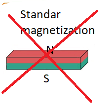
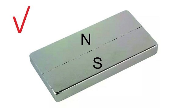
So I came to the conclusion that the best arrangement is to put my magnets upright, and make their magnetization different from the conventional one.


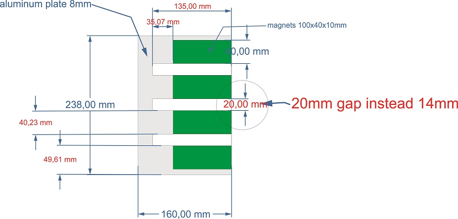
In this way, with 4 rows of magnets I can drive 3 stators. Of course, with less intensity than if you put a single stator and two iron discs, but with sufficient flux density, and even for the two external rotors of the set, these two can be mounted on two iron discs to support the set.

And i can imagine that using double layer winding on each stator and connecting in series the outputs of the rectifiers i could get a very good voltage at very low rpm, and with the massive amount of stators and the 20mm gap between the rotors i wouldn't suffer from overheating excessive of the set for an average power of 400 watts of output.


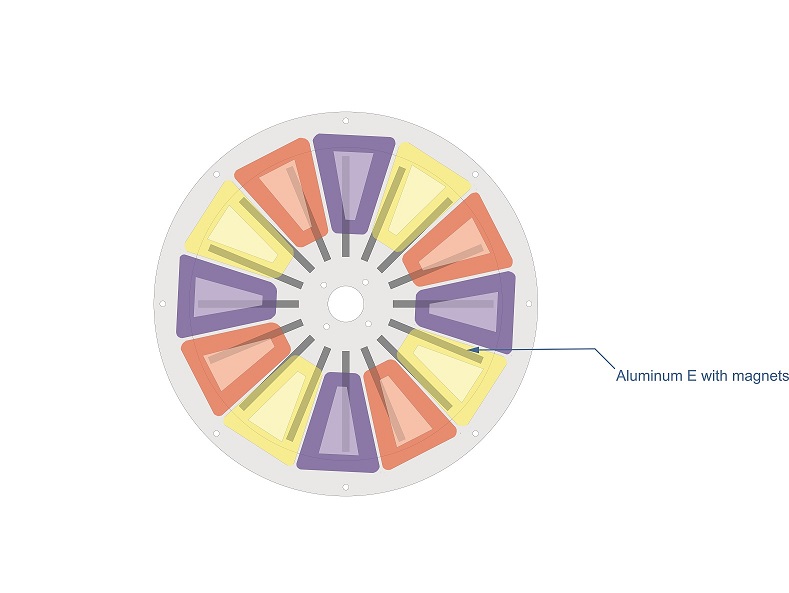
thats is the image with only a layer of coils, would be two layers to cover more surface of the disc with copper. 7mm tick each layer of coils. around 15-16mm tick the whole stator.

The generator will have massive quantitys of copper ,and massive quantity of magnets.
With that in mind I'm hoping to get the generator to put out at least 14-15 volts at 60 rpm. And about 300 watts. ( i can play with the conections at the exit of rectificators betwen the stators to reach the more adecuate voltaje and current).

It is necessary to clarify that I have in my possession 2 radial commercial type generators, with 600 watts of power at 500 rpm, one is for 12v the other for 48v, and although they are quite adjusted to the power marked by the manufacturer, I could not make a transmission that will take me from 60 rpm to 500 without losing much rotor energy in speed conversion. And that also those alternators probably  would cook on the first  stormy day (actually inclusive i am only using a couple of hoverboards in paralel for to do the tests in the prototype)  That's why I'm going to play with an oversized alternator to make sure it doesn't overheat too much on stormy days.

The turbine will have around 4.8 meters in height, 3.14 meters in wide. I have a prototype at scale, of 2.2meters x1.7 meters and gave 70-80 watts in 20k/h wind. That is enough results for me to try the jump in scale for a more reasonable use of real generation.

But because I am defining the parameters of the aluminum E to be machined in China (I am making all the components in China to order) and seeing that in this forum they have made very crazy ideas and not so much all kinds of generators. Maybe someone in the past tried to do something similar to this generator concept and failed in X issue and it would be nice to know to correct before investing thousands of dollars in parts that eventually would not work as expected.
Only in magnets I already have to spend 2000 dollars to have enough magnets for 3 generators. So it scares me a lot not to be considering something that maybe someone already tried before and for X reasons it didn't work.
  15152-215154-4


MattM

  • Hero Member
  • *****
  • Posts: 1178
  • Country: us
Re: new axial design multirotor
« Reply #1 on: January 14, 2023, 04:46:35 PM »
So you are running a multi-stator generator?

leviatan

  • Newbie
  • *
  • Posts: 46
  • Country: uy
Re: new axial design multirotor
« Reply #2 on: January 14, 2023, 06:08:09 PM »
yes, or is a multiestator, or i need to do a bigggggggg disc to acomodate 36 coils of that huge size. And a big disc involve ticker materials to hold the structure without risks of bending. Ticker materials involving steel is equal toa whole exesive weight for the generator. Then my choice is to produce a multiestator/multirotor design to save weight and size on design (and some magnets in the proces).
 I saw some big rotors with low rpm from a guy in brazil, but only with to see the size of the discs i can guess the weight is near of 100kg or more. I try to down the weight to more moderated 35-45 kgrs maximum. And the use of that kind of "E" in aluminum to atach the magnets will save a lot of weight. Because in a standar contrucction of axial PMGs, a disc of steel of 45-50cm or a bit more, with enough tick to not bend easy,  will weight easily  10krs each disc. then 4 discs of steel to hold the magnets will had 40kg+4 stator with the coils+the bar threads+axis+mounted bearings.... i will be in the sames 80-100krgs. Whit this way to atach the magnets i believe i can save a lot of weight and a construction withouts risk in the asemble (i saw the videos when the builders asemble the discs and is very easy to have a accident in that process, and the risks are increased when the pmgs are biggers).

electrondady1

  • SuperHero Member
  • ******
  • Posts: 3120
  • Country: ca
Re: new axial design multirotor
« Reply #3 on: January 15, 2023, 09:32:23 AM »
hello.
i am distracted from building windmills at this time since an invasive Chinese insect has killed all my ash trees.
when i am finished with these trees i plan on building a squirrel cage type drag windmill. 4'x8'
i prefer this type because the torque load is more constant.
big savonius type blades coming in and out of power positions put uneven loading on the machine.
i can't speak to your alternator design it is unconventional by using no iron backing for your magnets.
 
with a vertical axis  machine you end up with a large rotating body at the base of the machine.
you can build a small alternator and use that rotating body as a drive wheel
or use that large rotating body as the alternator itself.
the crossing speed of the alternator is the key to power production.


MattM

  • Hero Member
  • *****
  • Posts: 1178
  • Country: us
Re: new axial design multirotor
« Reply #4 on: January 15, 2023, 09:52:51 AM »
Well, there are a few things to consider. 

1. You need to ionically isolate your magnet material from the aluminum.  I assume you will seal up your magnets in the final build.
2. Conductive metal, not just iron, is impact by moving through electromagnetic forces.  Your plates will need to be stiff enough to overcome those repelling forces.
3. Assembly looks like it could get complicated on you.  Is it pretty much permanently tied together when assembled?

Other than that, looks like you have a plan.  You can build the iron into your stator rings, rather than the plates that hold your magnets, if you later choose to go that route.

leviatan

  • Newbie
  • *
  • Posts: 46
  • Country: uy
Re: new axial design multirotor
« Reply #5 on: January 15, 2023, 03:34:06 PM »
yes i guess i will glue with epoxu the magnets to the E of aluminum. I hope that would enough to save the magnets of parasit current that produce corrosion betwen different metals.
The E will have 6mm tick in first instance, i am waiting the complete quote of the chinese company about the difference in cost using 6 or 8mm.

Regarding  the assembly, the stator inner hole will have about 220mm in diameter, the E will be 160mm wide, I did a simulation in Corel and the 16 "E" should be able to enter through that hole (which will decrease as I stack the plates).
Use field check cards to see how wide the field is from its point of exit, and the field lines separate by more than 45º as they leave the edges of the magnet. That's why (beyond a different and safer way to assemble the rotors) the magnets are standing up, because I need to make sure there would be no interference in the coil at the moment of excitation. That is to say, I need to make sure that when the field begins to cut one of the legs of the coil, it does not continue exciting the previous one and generates losses due to short circuits in the direction of the pulsed current.

On the other hand, also the fact of being standing ensures a little more intensity of the magnetic field than if they were lying down, with which I hope they can get a good cut of the field lines through the 20mm space between the rotors. although I'm not going to buy the highest quality magnets: with grade n35 I hope to get enough field, without raising the cost of the magnets too much. Because after carefully studying the differences in power between the various grades, I came to the conclusion that it is preferable to increase the size of the magnetic material than to choose the one with the highest intensity in a smaller size (because prices jump non-linearly between the different grades).

In any case, I'm going to bring a couple of samples before they cut off my entire order (because there's no going back). If I discover that with grade n35, despite being standing, they do not generate a sufficient field, then I will discuss with the company the difference in prices with a higher grade.

My biggest concern is that someone else has already tried this arrangement and assembly of rotors and has encountered a difficulty that I have not calculated or expected. And since here they have tried almost everything, perhaps someone could warn me of some topic that I have not been able to discover in my tests.


MattM

  • Hero Member
  • *****
  • Posts: 1178
  • Country: us
Re: new axial design multirotor
« Reply #6 on: January 15, 2023, 06:42:30 PM »
Also remember your magnets will not tolerate moisture.

Adriaan Kragten

  • Hero Member
  • *****
  • Posts: 1158
  • Country: nl
Re: new axial design multirotor
« Reply #7 on: January 16, 2023, 03:47:50 AM »
Whatever design you make, it must be such than the flow of the magnetic flux is optimal with respect to the coils. This means that if the heart of a magnetic north pole is opposed to the left leg of a coil, the heart of a magnetic south pole is opposed to the right leg of a coil. In this case the voltages generated in both legs will strengthen each other. This principle is explained in chapter 9, "Second way of explanation" of my public report KD 341 for an 8-pole axial flux PM-generator with a 3-phase winding.

In the first photo you show that the magnet is magnetised in parallel to the magnet width and not in parallel to the magnet thickness like it is normally done. If the second photo you show that the magnets are mounted such that the magnet width is in parallel to the air gap. I think that this results in the wrong magnetic flux pattern. So you should make a picture in which you show the magnetic flux pattern and this picture must demonstrate that the north pole is opposite to the left leg of a coil if the south pole is opposite to the right leg. If you have ordered many magnets with this uncommen direction of the magnetic field and if your generator migh not work, such magnets can't be used for a normal axial flux generator and all investment is lost.

I have looked at the lowest picture and it seems that you are expecting that the magnetic flux is flowing axial. But this flux will be rather small as you don't use iron disks at the top and at the bottom. However, there will be a rather large tangential magnetic flux in between adjacent row of magnets and this magnetic flux isn't flowing through the coils. If you want to have a rectified DC current with only a small fluctuation, the distance in between the magnets must be 1/2 the magnet width. But in your lowest picture, the distance is very much larger, especially at a large radius. A voltage is only generated as long as the radial part of a coil is in between two magnets. So one phase will generate only an AC voltage during a very short part of the time and the rectified DC voltage will therefore fluctuate strongly.

It is possible to design an axial flux PM-generator with more than one stator but then the construction of the armature and stator sheets should be similar to that of a generator with only one stator. You only pile stators and armatures on top of each other. However, mounting of those armature and statior layers isn't easy.

« Last Edit: January 16, 2023, 07:03:21 PM by Adriaan Kragten »

leviatan

  • Newbie
  • *
  • Posts: 46
  • Country: uy
Re: new axial design multirotor
« Reply #8 on: January 16, 2023, 12:44:31 PM »
15155-015156-1

May be you not placed so much attention to the draws and the idea. I m tryng to think outside the box.
I can use the most tipical design doing a couple of steel discs with the diammeter for contain the 36 coils of that size (1,5 meters of diammeter.... imagine the weight of a steel plate of that size) or i can  try a mutlrotor design. But inclusive beign a multirotor the weight of  4 steel plates of 51 cm diameter to hold my magnets, is a extreme weight only for the steels discs (probably 40-50kg only in that parts, and that adding holes to save weight, that means extra costs also).

I cant use steel material for the E because the flux would run by the E and not for the air from magnet to magnet.  I Cant use the E with the shape of severals C joined and the magnets in the standar position for commoun axial PMG,  because i need a super reinforced material to hold the atraction betwen the magnet without risks of bending (or the added problem of to use only one magnet in the central rotors, and a system to hold very good aligned in the instalation, would complicate the things using severals C mounts,  the E cuted with laser  and standup magnets will be my best chance to got  perfect alignement of all parts)

Then left or to do a multi rotor system with a weight enough to have accident in the  asemble of the parts and in the transport of the PMG and in the instalation of the PMG in the turbine.
Or i can use the E design to have a strong piece to hold the magnets with a low weight and easy asemble.
 
The flux will not run 5cm in the way to conect with a oposite pole, if have other oposite pole at only 2cm.

The only part when i will use steel plates are the upside and downside plate of the whole set to atach the E to a strong base. But that plates will have only 3mm or less (discarded plow discs) because the atraction force of the magnets will be loaded only in the frame of the aluminum E, not in that plates.

About the low exitation time in the coil i guess wil be enough, you can see in the image the 2 layers of coils ( will have separated rectificators, then i can conect at the exit in paralel or series) will cover almost all the surface of the stator and with a strong field without any possibility of a short circuit betwen legs of the coils i will have ZERO looses in that delicated subject.

And the field  projected of the magnet not is like the tick of the magnet. The magnet have 1cm tick but the field proyected betwen two magnets with 20mm gap is like 3.5cm wide or a bit more inclusive (use a inspect card to see the real efect of the fields on the air). Then you have a reasoneable field over the leg of the coil.
May be like you said a oposite direction of the current with a magnet in one leg and the other in the other leg is much better for the production (but if happen in all the coils at the same time also can produce some cogin effect) but also means more magnets (the more expensive part of the whole set). And for other side if i do a 100% extreme efficient generator that means all the parts will suffer extra heat like result of the large production with components squeezed to the maximum.

This PMG need to be made fo produce only 300-500 average watts, but with very low RPMs and to have the strenght to hold a furious stormwind without damage by overheat. But that i not  searching for the most effective way to produce the watts with the less components posibles, because that work for a specific ratio of torque or rpms, but when conditions changes... the problems are there surely...
Then big coils, big magnets, zero losses of shortcircuits coils, zero looses in iron cores, and a total of 72 coils (24 for each stator) its my choice to got the results.
Please see more carefully the draws, and you will agree with me the flux direction will not be a problem with the design.
My concernt is about other things like problems with the corrosion on the magnets and in the E, the best option for epoxi for the stators, probably a good epoxi paint to cover the magnets and the E when are asembled, and the right size of the wire for to do the coils ( i dont know if a 1mm wire would be enough or if a need confidence in the design i need to oversize the wire more)


« Last Edit: January 16, 2023, 02:50:01 PM by leviatan »

MattM

  • Hero Member
  • *****
  • Posts: 1178
  • Country: us
Re: new axial design multirotor
« Reply #9 on: January 16, 2023, 03:31:46 PM »
With 20mm space between plates, you aren't looking for many turns per coil.  Probably room for 30 if you have tight clearances. 

leviatan

  • Newbie
  • *
  • Posts: 46
  • Country: uy
Re: new axial design multirotor
« Reply #10 on: January 16, 2023, 04:49:12 PM »
15157-0

7mm tick x26-28mm wide of each leg, if i use 1mm wire,  i can calculate 5 wires in height 20 wires in wide= 100 turns on each coil.  If i change the wire tick the turns will be down quickly, but i dont know how much is the ideal tick of the wire to generate something at lower rpm and hold the risks of burn in a heavy storm. Should test several wire ticks, but at the moment im only have 0.70 wire.

 In this days i will take some vacations until the next week, when i come back home, i will finish the hand crancked coil winding (only lack the turns counter) and ill do a sample in 0.7mm to test the generation with the lathe and the litlle samples of neo bars.

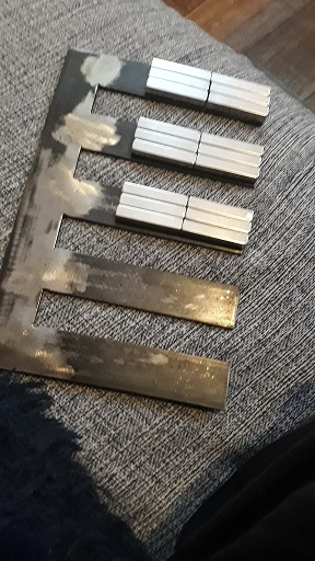
My sample blocks not are equal to a two solid piece of neodymium of 100x40x10mm, but 8 blocks combinated of 50x10x10mm can obtain a good field to test. Are the blocks in the earlier images, because are perfect squares, i can stack one over other and simulate a block with my desired magnetization direction, i only need to place a litlle  iron bar betwen the joint of the two sets of blocks to manage better the forces of repulsion in that point. And with that system i am obtaining a similar (not equal because the magnets are closing circuits fields betwen theys) field of a two blocks of 100x40x10mm to do a test with the 0.7 wire and see what happen.
« Last Edit: January 16, 2023, 06:09:09 PM by leviatan »

MattM

  • Hero Member
  • *****
  • Posts: 1178
  • Country: us
Re: new axial design multirotor
« Reply #11 on: January 16, 2023, 06:33:12 PM »
18 gauge is probably good for 5-6 Amps at 105v.  What is your target?

Edit:  I see you are looking at an overall 300W at 15v.  Each phase will definitely be approaching its safe range in a short run.  Doesn't sound like a good choice coming down the tower.  Maybe you should aim for a 48v system.
« Last Edit: January 16, 2023, 06:53:17 PM by MattM »

leviatan

  • Newbie
  • *
  • Posts: 46
  • Country: uy
Re: new axial design multirotor
« Reply #12 on: January 16, 2023, 07:13:45 PM »
lets see what current and volt produce the test and i then will see what to do later.

Adriaan Kragten

  • Hero Member
  • *****
  • Posts: 1158
  • Country: nl
Re: new axial design multirotor
« Reply #13 on: January 17, 2023, 05:25:11 AM »
If you want a generator with a high torque level at low rpm you should start with a geometry which is optimal for a normal axial flux generator. There are good reasons why these generators are built in a certain way. These reasons are explained at earlier discussions on this forum. I will now explain different options on how the torque and power level of an optimum design can be increased. Therefore I take the coil and magnet configuration of the 8-pole generator with a 1-layer, 3-phase winding as given in the lowest picture of figure 5 out of report KD 341. So this generator makes used of sixteen neodymium magnets size 30 * 20 * 10 mm glued at the inside of two iron armature disks at a pitch circle of 90 mm. The stator winding contains six coils. Assume that the air gap is taken the same as the magnet thickness, so 10 mm. Assume that this generator supplies an electrical power P at a rotational speed n.

A) Assume that two of these generators are placed on the same shaft. So now one needs 32 magnets and twelve coils. It will be clear that now the power is 2 * P at n. So doubling of the power requires double the amount of magnetic material if the flux density in the air gap is the same and double the amount of copper.

B) Assume that now a 16-pole generator is made using the same magnets on a pitch circle of 180 mm and twelve coils with the same wire thickness and the same number of turns per coil. The speed of the magnets at the pitch circle is double that of the original design and so the voltage generated in a wire of a coil will be double too. You have the double number of coils per phase and so the total phase voltage will be a factor four higher. So now the power will be 4 * P at n. So option B uses the same amount of magnetic material and the same amount of copper as used for option A but supplies two times more power. The maximum torque level is therefore also a factor two higher.

C) Assume that now an 8-pole generator is made using sixteen magnets size 60 * 40 * 10 mm at a pitch circle of 180 mm. The air gap is maintained at 10 mm. The stator has six coils. The width of a coil leg is doubled and the lenght of a coil leg is doubled too but the thickness of coil leg is kept the same. The generated voltage is doubled because of the larger speed and it is four times larger because of the larger coil and so the total voltage of this generator is a factor eight larger that that of the origional design. So now the power will be 8 * P at n. The power at a certain rotational speed is therefore a factor four larger than option A. However, the required amount of magnetic material and copper is a factor two larger than option A.

D) Assume that now an 8-pole generator is made using sixteen magnets size 60 * 40 * 20 mm at a pitch circle of 180 mm. The air gap is now increased to 20 mm. The width, the thicknes and the lenght of a coil leg are now doubled. The magnet speed is doubled too. So the generated voltage in a coil is a factor sixteen higher than for the original design. And the power is therefore 16 * P at n. The power at a certain rotational speed is therefore a factor eight larger than option A. However, the required amount of magnetic material is a factor four larger than option A.

These four options show that option A is not a good choice as it uses more magnetic material and more copper for a certain power P at a certain rotational speed n than options B, C and D. So if you want a generator with a high maximum power and torque, you should increase the diameter of the pitch circle.

But you should realize that the need for such a big generator is the result of the bad choice of your windmill rotor. A normal 2-buckets Savonius rotor is partly a drag and partly a lift machine and therefore it has a much higher maximum Cp and a much higher optimum tip speed ratio than a pure drag machine. It is partly a lift machine because there is a flow through the rotor. But if you use three buckets, this flow through the rotor is almost zero and then it becomes a pure drag machine with a much lower maximum Cp and a much lower optimum tip speed ratio than a 2-buckets Savonious rotor (see report KD 416 for drag machines and report KD 599 and KD 703 for Savonius rotors).

MagnetJuice

  • Hero Member
  • *****
  • Posts: 558
  • Country: ca
Re: new axial design multirotor
« Reply #14 on: January 17, 2023, 06:48:13 PM »
There are some errors in Adriaan's calculations.

In option C, the area of a 60mm x 40mm magnet is four times larger than a 30mm x 20mm magnet. Therefore, the magnetic material is four times larger, not two times.

In option D, the volume of a 60mm x 40mm x 20mm is eight times the volume of a 30mm x 20mm x 10mm magnet. Therefore, the magnetic material is eight times larger, not four times.

Nevertheless, that was a very good explanation of the advantages of using larger diameter rotors. Especially when using a Savonius, because the speed is just not there.

Adriaan also mentions the fact that a two-bucket Savonius is more efficient than a three-bucket. Blackwell, Sheldahl and Felts working with Sandia Labs confirmed that with extensive testing in 1977.

Other researchers have tested the difference between two, three, and four buckets and came to some interesting conclusions. This is what they found:

1 – TSR is higher for four-blades and three-blades, but only at lower speeds. At higher speeds, the two-blades has higher TSR.

2 – Four-Blades has a higher torque than two or three blades and less torque ripple, but it has more drag.

3 – Two-blades has more torque ripple, and vibration, but less drag.

By looking at those findings, it appears that the best solution is to have a two-blade rotor mounted on top of another two-blade rotor at 90 degrees.

That configuration will have high TSR at low speed as well as at high speed. The wind will see that configuration as four blades; therefore, it will have more torque and less torque ripple with less vibration.

leviatan, a while back I designed an alternator for a Savonius. It was designed to start charging a 12-volt battery at 45 RPM. I was looking at it last night and I think that it can be adapted to your needs. When I get some time, I’ll take a close look at it.

Also, with all the research that you have done, I am sure that you are familiar with the Benesh blade profile and with the modifications and testing that Rahai did with the Benesh profile. If not, you should look it up.

Ed
« Last Edit: January 17, 2023, 07:36:34 PM by MagnetJuice »
What can I do TODAY that would make TOMORROW a better world?

leviatan

  • Newbie
  • *
  • Posts: 46
  • Country: uy
Re: new axial design multirotor
« Reply #15 on: January 17, 2023, 10:54:19 PM »
Hi again. Lets talk about Adrián answer, dint matter he could do wrong the calculates about the quantity of magnétic material. The main problem is he dont are understanding the draws. I have a projected stator of 65cm diameter, that is a huge size and the límit that i can reach. More than that is exesive for my like.

But because i dont know ( until i do a test of one col in the lathe) if that size and cols number would be enough to works at very low rpm, i am designing a new style of multirotor,  with less eficience that the most clásical ( and tested) designs but with the very important advantage of have a weight very contained.
At first look a low weight for the generator could not sound so important, but  all parts in a turbine are related , and more weight to move, means more inerce force to beat.

When the wind is continuosly changing on direction and speed, a low inerce of the whole parts means less loses in the charge of cinétic power the whole turbine. By that you cant see a half oil drums turbines producing something in any videos on you tube. Theys only spins without charge, and the reason is with the whole weight of that kind of turbines the wind need a lot of time to charge cinétic power, and probably when are done the wind decrease his speed and the turbine only consume the rest of cinétic power on 4 or 5 turns more and other time to wait the next jump in wind speed to repeat the fail process.

Then, the weight of a generator rotor matter. A lot if you try to use a savonius in low wind conditions.
If the planes would be constructed to survive the crashes, theys dint fly.

Then i am having in account the whole subjects involved in the eficience of a turbine, the things not are splitted ones over others.

May be later of to do the first tests i reach the conclusión with only one stator disc and two layers of coils i got enough power at very lows rpm. In that way i would use a more clásical design, may be with touchs of my original idea, but similar construction to the most knowed designs.

And about the benesh rotor, i saw the subject ( i saw any design based on savonius) and not convinced me for nothing.
The tree blade savonius Is the schulz design, is very similar to the savonius in the subject of flow over the center of axis.
Inclusive i believe he got more advantage of that efect than a savonius of two blades.

If i would have chances to produce a one stage twisted savonius in the size proyected (5 meters height×3wide) i believe i would try that. But normal savonius need the two stages to solve the problem of jumps in the torque, and that two stages means more material, at the point to have almost the same weight of a 3 blades one stage, but more ugly to see, and with more pieces than a 3 blades one stage.

A thing to consider when exist comparisons betwen 2 or 3 blades, the 3 blades is normaly 50% more weight than a 2 blades twisted, and when the rotor spins at high level of speed in a túnel of wind , less blades is equal less drag, and that cause more eficience on the tests.

But when you turn a turbine BIGGER in the normal average conditions of the wind (14-20k/h) the turbine will spin very slow, and you will take a lot of profit of to have more blades taking any wind posible in more wide variety of angles.
By that reason i guess you can see on web a lot of little savonius twisted designs and and 3 blades savonius ( not ever schulz option) like comercial options, but you cant see barely other designs ( lenz, benesh, and others options) .

When you run a scale prototype of 30-50 cm height and 20-40cm wide in a wind túnel you not are replicating exactly the conditions of work in the real world.

I test my first mini prototypes of the schulz  rotor (40cmx15cm) and with a wind of 21-22k/h, and without charge he can spins at 900rpm. But when i pased to the 2.2meters x 1.70 meters, at same wind speed and without charge he could reach barely 80-100rpms. Of course the torque rise a lot. But when persons ( with the best intentions) do test in wind túnels of little prototypes with very high winds speeds, the cientifical study is a complete fail because theys dint take in account the changes in rotational speeds when size of the prototypes grow to the real scale.

By all that, and because i have a proof with video a the schulz design producing a very modest 55watts in winds 14-20 k/h and with a couple of overboards motors like generators (not the best for sure) i believe schulz rotor is the best option to scalate a turbine to the production size, with a modest invest and a easy asemble.

But if i have a vawt turbine design of 5m×3m with a strong and reliable structure and a weight of only 140-150kg for the mobile parts, i not like to install in it, a generator with a weight of others 100 or more kilograms for not think in one more wise alternative for the design of a axial pmg, if are posible.

I not violating any rule of the magnétic fields on the design, i am changing the best eficience option of design for a huge save on whole weight, holding the desired target of production and taking security because the eficience not is the best neither, the components will have margin to support hard conditions without any complex systems to manage that rare situations.


MagnetJuice

  • Hero Member
  • *****
  • Posts: 558
  • Country: ca
Re: new axial design multirotor
« Reply #16 on: January 18, 2023, 12:36:44 AM »
levatian,

I get the feeling that you didn’t come here to ask for help. It looks like you came here to tell us about your new and better Savonius and your sophisticated alternator design.

Did you read any of what Adriaan or I said?

It seems that your head is so full of ‘knowledge’ that there is not any room for anything else to get in.

I designed an alternator that can output 900 watts at 45 RPM and weighs less than 60 Lbs. The diameter is about 18 inches, and the magnets would cost a total of 215 US$.

However, you would not be interested in something like that, because it is a 'conventional' axial flux design, and the magnets are mounted on steel.

I am not going to give you any details about it, because all you are going to do is tell me that your design is better.

Please stick around here. I would love to see how your project performs.

Good luck,

Ed
What can I do TODAY that would make TOMORROW a better world?

Adriaan Kragten

  • Hero Member
  • *****
  • Posts: 1158
  • Country: nl
Re: new axial design multirotor
« Reply #17 on: January 18, 2023, 04:24:13 AM »
There are some errors in Adriaan's calculations.

In option C, the area of a 60mm x 40mm magnet is four times larger than a 30mm x 20mm magnet. Therefore, the magnetic material is four times larger, not two times.

In option D, the volume of a 60mm x 40mm x 20mm is eight times the volume of a 30mm x 20mm x 10mm magnet. Therefore, the magnetic material is eight times larger, not four times.

Ed

No, there are no errors in my calculations because I compare options B, C and D with option A and not with the original design. The original design uses 16 magnets size 30 * 20 * 10 mm and so the total magnet area is 16 * 30 * 20 = 9600 mm^2. Option A uses 32 magnets size 30 * 20 * 10 mm and so the total magnet area is 32 * 30 * 20 = 19200 mm^2. Option B uses the same number of the same magnets and so the total magnet area is also 19200 mm^2. Option C uses 16 magnets size 60 * 40 * 10 and so the total magnet area is 16 * 60 * 40 = 38400 mm^2 which is 4 times the area of the original design but 2 times the area of option A.

The original design and options A, B and C all use 10 mm thick magnets and so the magnet volumes are proportional to the magnet areas. So the magnet volume of option C is two times the magnet volume of option A. Option D uses 20 mm thick magnets and so the magnet volume of option D is two times the magnet volume of option C and so four times the magnet volume of option A. So this calculation shows clearly that a generator with two stators on the same axis uses two times more magnet material for the same power than using one stator and a larger diameter of the pitch circle. The difference in power becomes even a factor four if you compare a generator with four stators at the same axis with a generator with one stator and the same number of the same magnets on a four times larger diameter of the pitch circle.
« Last Edit: January 18, 2023, 05:02:01 AM by Adriaan Kragten »

MattM

  • Hero Member
  • *****
  • Posts: 1178
  • Country: us
Re: new axial design multirotor
« Reply #18 on: January 18, 2023, 06:56:09 AM »
Since he wants torque, he can run a belt or chain to literally increase the rotational speed of his generator without increasing the needs for additional magnets.  Sounds like the ideal situation for a motor conversion.  Scrap the thousands on fabrication of a Rube Goldberg machine and go for off the shelf rebuild.

I'd suggest reading posts by Dave B and bigrockcandymountain about their conversions.  mbouwer also posted about gearboxes awhile back.  Could save lots of heartbreak and cost far less.
« Last Edit: January 18, 2023, 07:11:12 AM by MattM »

MagnetJuice

  • Hero Member
  • *****
  • Posts: 558
  • Country: ca
Re: new axial design multirotor
« Reply #19 on: January 18, 2023, 11:56:57 AM »
Yes Adriaan, you are correct.

I assumed that option A had the same number of magnets as the ORIGINAL design. I failed to see that in option A, you had already doubled the magnets.

I am sorry about that.

Too many assumptions. This stuff is getting to be confuser and confuser.  :D

Ed
What can I do TODAY that would make TOMORROW a better world?

joestue

  • Hero Member
  • *****
  • Posts: 1763
  • Country: 00
Re: new axial design multirotor
« Reply #20 on: January 18, 2023, 01:25:48 PM »
for two systems operated at similar conditions, axial flux motors can produce a higher torque density when you are limited by the machine's weight or volume. this increase in torque comes at a cost of higher losses.

that being said, radial flux, which is the traditional motor design, are more efficient than axial flux machines, they just weigh more unless you can make the rotor hollow, and that wasted volume makes the total motor volume larger for a given torque density. otherwise they would be very similar, and you can overcome that with a multi layer radial flux machines, they are just difficult to manufacture.

but its really simple to understand why: the radial flux machine has mostly rectangular or square coils. axial flux machines have trapezoids. for a given surface area, the axial flux machine has a longer coil length because its a trapezoid. also, the flux density's force on the inside radius does less work on the machine because its a smaller radius.
My wife says I'm not just a different colored rubik's cube, i am a rubik's knot in a cage.

leviatan

  • Newbie
  • *
  • Posts: 46
  • Country: uy
Re: new axial design multirotor
« Reply #21 on: January 18, 2023, 04:15:14 PM »
In first place this is a forum to discuss ideas about eólic. No body should feel insulted because his ideas not are being well received.
Second: the eólic science is a subject very complex.
If would easy should exist hundreds of companys doing wind turbines with certifications of third companys  about the verification of  the claimed power.
Or should exist hundreds of videos of sucesfull wind turbines proyecta. Or inclusive the companys dedícated to the vawt wind turbines would continúe existing later of 5 or 6 Yeats of life.

All that clues pointing the subject of to make a wind turbine with reasoneable production ratio is a very dificult área of work.
The most of the persons only spent in cardboard of some sheets of plywood when try to  do a scale or full size vawt. Then the results trend to be bad to worst.
Having in account the results of bad ideas made with wrong materials and worst results, the design of a vawt not is mater of a feeling of one month.
Need to be thinked and rethinked a lot of times, and very much of the teorys that a first look can work need to be tested first in scale, and find what is wrong with the teory vs the practice.

I found the transmisión not are the optimal systems to atach to one generator, depending of the perfection of the system, the loses can be from 10-15% to the 50% . Then i am tryng to do a pmg that work a very low rpms without the help of a transmisión.
A pmg of real very low rpm( for 60 rpm and 1000w   by example) cost no less of 4000-5000 usd in china.
Then i think that not is a afordable price considering the material cost.

What i can do for less of that, is what i am tryng to do. Need to sport other rpms ratios until 300 by example, without burn, and be low weight, and with low risks in the asemble and instalations.
All that selected features force to change the commoun axial design to a most diferent thing.

If somebody thinks are inclusive better ways to reach all that features with other design, well here is the place to share ideas. And nobody should feel like a insult his ideas would discardeds by others.

I can acept somebody think i am dreaming a new design of pmg,  but at the ends matter the results not the teory.

Then i can acept magnet juice could to do a design of axial pmg, with very low rpms target and worked, but at the all what i saw on interne (homemade)  need no lees of 200 rpm like minimal speed to produce useable current. Then for me would be a good help to see that design, how much materials were involved and the strenght of the whole set. And that not means my idea wouldnt work also.
I defined this parameters because all what i saw on internet ( bu years) dint work in very low rpms. Then if you magnet do that and worked share the design because i cant found any working device homemade with that specific features.


JW

  • Development Manager
  • Super Hero Member Plus
  • *****
  • Posts: 4049
  • Country: us
    • Flashsteam.com
Re: new axial design multirotor
« Reply #22 on: January 18, 2023, 05:51:10 PM »
Quote from: Leviatan
Then i can accept magnet juice could to do a design of axial pmg, with very low rpms target and worked, but at the all what i saw on interne (homemade)  need no lees of 200 rpm like minimal speed to produce useable current. Then for me would be a good help to see that design, how much materials were involved and the strenght of the whole set. And that not means my idea wouldnt work also.
I defined this parameters because all what i saw on internet ( bu years) dint work in very low rpms. Then if you magnet do that and worked share the design because i cant found any working device homemade with that specific features.

 &need no lees of 200 rpm like minimal speed to produce useable current.&

That sounds abit low. what diameter is your rotor.


JW

  • Development Manager
  • Super Hero Member Plus
  • *****
  • Posts: 4049
  • Country: us
    • Flashsteam.com
Re: new axial design multirotor
« Reply #23 on: January 18, 2023, 06:11:17 PM »
I have been working with a movement related to angular momentum in some recent calculations. Vector and angle usually don't have the flux density to do what your describing.


leviatan

  • Newbie
  • *
  • Posts: 46
  • Country: uy
Re: new axial design multirotor
« Reply #24 on: January 18, 2023, 06:25:18 PM »
A savonius style turbine with 3meters or more in wide, cant run in a average (and modest speed)  wind of 20k/h at more than 60 RPMs. Then the pmg should be  able to produce 250-300 watts in that lows rpm.  I reach 80 watts at 12-15v with the first prototype and hoverboards motor like pmg (and a transmisión 10 to 1) Then with a turbine 4 times more bigger in area should produce at least 300 watts.  i am  tryng to do the pmg to produce current without transmisión and that is the reason to use 3 stators and 72 coils to got some of current with a very low angular speed in the pmg.

JW

  • Development Manager
  • Super Hero Member Plus
  • *****
  • Posts: 4049
  • Country: us
    • Flashsteam.com
Re: new axial design multirotor
« Reply #25 on: January 18, 2023, 06:30:18 PM »
what are the thickness of your magnets.

leviatan

  • Newbie
  • *
  • Posts: 46
  • Country: uy
Re: new axial design multirotor
« Reply #26 on: January 18, 2023, 07:08:43 PM »
100x40x10mm, but the magnetización direction is over the short axis of the magnet. Then the surface área of the magnet over the coils is a rectangle of 100mmx10mm and 40mm of tick.

JW

  • Development Manager
  • Super Hero Member Plus
  • *****
  • Posts: 4049
  • Country: us
    • Flashsteam.com
Re: new axial design multirotor
« Reply #27 on: January 18, 2023, 07:36:31 PM »
Quote from: Leviatan
A savonius style turbine with 3meters or more in wide,

Ok so over 16ft dia of the rotor.

" NMR is not an imaging technique but rather a method to provide spectroscopic data concerning a sample
placed in a small volume, high field strength magnetic device. In the early 1970s,
it was realized that magnetic field gradients could be used to localize the NMR signal and to generate images that display magnetic properties of the proton, reflecting clinically relevant information"


MattM

  • Hero Member
  • *****
  • Posts: 1178
  • Country: us
Re: new axial design multirotor
« Reply #28 on: January 19, 2023, 06:09:55 AM »
It sounds like most of the criticism surrounds your magnet arrangement.

Instead of stacks of three long magnets, where the flux is spread thin on each side of the fingers, perhaps you would be better to go one shorter, more powerful cube the width of the finger.  Your coils could be smaller, too.

Another thought is that you could use a spacer between vertical pairs, so more flux is available where it counts.  Could get tough to hold them in place.

Adriaan Kragten

  • Hero Member
  • *****
  • Posts: 1158
  • Country: nl
Re: new axial design multirotor
« Reply #29 on: January 19, 2023, 06:24:51 AM »
What finally counts is the required investment to generate one kWh at a certain wind speed. If you compare the best possible Savonius rotor with a well designed HAWT, the Savonius rotor will loose the battle for many reasons. The first reason is that the maximum Cp is much lower. The second reason is that the maximum Cp is gained at a much lower tip speed ratio lambda. This results in a much lower rotational speed for the same rotor diameter and wind speed and this requires a much bigger and so much more expensive direct drive generator. The third reason is that the rotor can't be protected against very high wind speeds by turning it out of the wind. The fourth and most important reason is that the required area for the buckets and the horizontal sheets is much larger than the swept area of the rotor.

So the required amount of material for the rotor is much and much larger than for a well designed HAWT which generates the same power at the same wind speed. These reasons make that it is a waste of time and money to develop Savonious rotors which generate electricity. I am telling this almost fourty years now but people, mostly without any aerodynamic knowledge, continue promoting them untill they have really built one and met all the disadvantages.

leviatan

  • Newbie
  • *
  • Posts: 46
  • Country: uy
Re: new axial design multirotor
« Reply #30 on: January 19, 2023, 10:17:26 AM »
I think inclusive the diference in materials is more huge than your calculates.
But a hawt need average wind speed very much highers than a vawt savonius to produce. The vawt dint produce disturbing sounds.
The vawt have very much wider ratios of wind speed to work, and if are strongly  constructed not need any system to hold high winds speeds. If a twister happen, the survive of the turbine will be the last of the worrys.
You can install a savonius in any place at any height and he will work dint matter if wind change direction and speed continuosly.
And as bigger is the savonius less rpms will run, then the exesive rpms would be a posibility in any big storm only, and the turbine can manage that with a tip ratio of less of 0.9.

You cant use a hawt in any place at any height, you cant place a device with disturbing sound near of neighbors.

And a last subject, important for me at least: a hawt is normaly ugly to see, a vawt is atractive to see on working, almost hipnótic.

I Will not like to have a hawt in my home, at change i love the visual impact of to have a vawt or more in my home.

Not is necesary comparate eficience betwen the two systems because are very diferent things, and where a system can work very well the other cant work.
 Then for urbane enviroments a savonius kind wind turbine can work, for other enviroments like the open field a hawt would be a better option if the eficience is the only thing to consider.

If the eficience would be the only thing important in the world (when a person choose a good) well... will dint exist more luxury cars, or big houses, or tríps of pleasure.
Diferent persons have diferent interests, and a luxury good can worth millions for one person, and nothing for other at his side.
Then when we are taking about wind turbines and specifically vawts, that last word means the efficience not is the main target on the discusión.
 Other things can be more determinants to choose a vawt vs a hawt.
Then to compare the theoretical diferences in efficience betwen a hawt and vawt not is the right discusion.  That is for other threads i guess.


leviatan

  • Newbie
  • *
  • Posts: 46
  • Country: uy
Re: new axial design multirotor
« Reply #31 on: January 19, 2023, 10:48:38 AM »
It sounds like most of the criticism surrounds your magnet arrangement.

Instead of stacks of three long magnets, where the flux is spread thin on each side of the fingers, perhaps you would be better to go one shorter, more powerful cube the width of the finger.  Your coils could be smaller, too.

Another thought is that you could use a spacer between vertical pairs, so more flux is available where it counts.  Could get tough to hold them in place.
The magnets on the photo are block samples of the only shape that i can use to try a replicate of a magnet of 100x40x10mm with my desired direction of magnetización. In efect i need to place a spacer betwen the two vertical layers for the tests with theys.
But more wider magnets means more wider coils if a search for zero flux in the oposite legs of a coil with the same magnet pole.

More wider coils holes need larger diammeters of the stator, and that 650mm is my límit ( and is a georgeous limit).

I have parameters of efficience what i like to respect and others that i prefer forget in the name of stetical issues.
 The more efficient for me would be to buy more  radials pmg at usd 100 in china, and the money invested on design my own pmg coreless, would invested in to increase the size of the turbine to compensate the transmisión loses with a 500rpm rated generator.

The most efficient woul be to import fotovoltaic paneles instead to produce homemade wind turbines.
The challenge is to design a thing at my own parameters ( because i found defects of design in other pioners designs) and see the results. Is good to discuss this subjects, new ideas can happen using ideas of others. By example i not had the smart idea of to use the lathe to test the coil production without the need of produce a complete rotor system. I took the idea from a advice to other user.
Then discusing advices can be worth sometimes. And if my idea dint work líke i expected we can left the leason for other builder about what was wrong.
The subject  is to have the capacity to understand if someone like the pink unicorns like system to got transportation, no one should be feel insulted if he not like a bicycle because is more cheap and easy to find and use than one unicorn and pink elsemore. 

Bruce S

  • Administrator
  • Super Hero Member Plus
  • *****
  • Posts: 5374
  • Country: us
  • USA
Re: new axial design multirotor
« Reply #32 on: January 19, 2023, 03:55:54 PM »
BEGIN MODERATOR MODE
All I'm a bit late to these posts, however let's all remember.
This is a let's be nice forum.

END MODERATOR MODE


Bruce S
A kind word often goes unsaid BUT never goes unheard