Author Topic: Feasibility of a tilted VAWT  (Read 1200 times)

0 Members and 1 Guest are viewing this topic.

MattM

  • Hero Member
  • *****
  • Posts: 1178
  • Country: us
Feasibility of a tilted VAWT
« on: February 07, 2023, 01:33:27 AM »
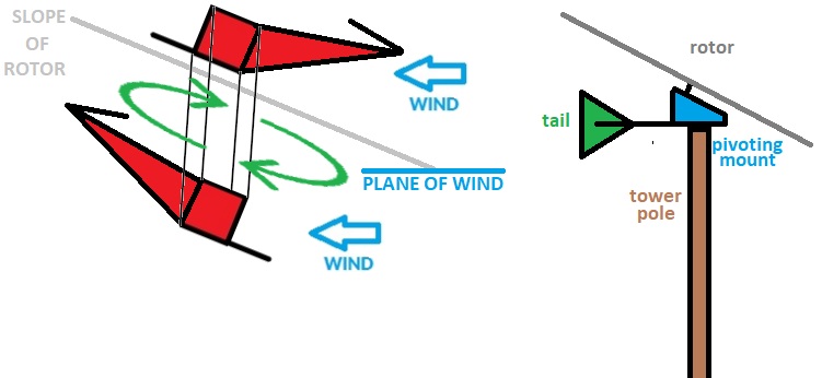
About a dozen years ago I created an accidental hybrid between a HAWT and a VAWT, where the blade moved along a sloped plane rather than horizontal or vertical.  I've been thinking about it ever since.  It seems plausible to actually get the drag from the blade moving in all 360 degrees of rotation if my thoughts are correct.  While not as fast rotating as a HAWT, I found the original to rotate quite a bit faster than a VAWT.  The concept should work both as a wide/skinny blade or as short/fat, although the raw RPMs will not be equal.15227-0

The original was only about 8 feet off the ground and would spin at speeds the HAWTs wouldn't even register wind.  It is directional, but with a slight offset between the pivot of the tower and rotor, it needs minimal tail.  The tail is really for stability to slow down its twitchy behavior, because it wants to instantly turn towards the wind origin.

The front stroke, is moving with the wind, so in essence its kind of a back stroke I guess.  The arm begins the stroke at the front dead center, so I'll refer to it as the front stroke. There are two key points of drag on the front stroke:  (1) the rear L channel, and (2) the nose V channel.  The air flow smoothly follows these channels from the tip to the center of the rotor for 90 degrees, then reverses to flow from rotor center to tip for the second 90 degrees.  The idea is not to truly stop the wind behind the blade, but rather to allow it to follow the channels.  Probably doesn't make a difference, but its a curious flow pattern.  Other designs seem to be better off when not blocking off air flow through the design.

The return stroke, in contrast, begins at back dead center and is generally moving into the wind.  I've been thinking that the front of the blade should really have a slight pitch up from the main arm of the blade, to give it minimal air resistance on the return stroke.  On the return stroke it actually continues to get pushed forward due to the wind deflection, like a sailboat would tack to move upwind.  My original project had a straight blade that worked extremely well, but it could have been better if it tacked.  Tipping the slope a bit more than the slope of the blade may enhance both strokes, but add drag in the return slope, so not sure it would add any advantage.

The original design had three arms.  There should be minimal interference from disturbed air between arms, so 6 arms could realistically work.  More arms would increase the weight, so 3 is optimal IMHO.

What are the opinions about this idea?
« Last Edit: February 07, 2023, 08:03:53 AM by MattM »

Adriaan Kragten

  • Hero Member
  • *****
  • Posts: 1158
  • Country: nl
Re: Feasibility of a tilted VAWT
« Reply #1 on: February 07, 2023, 07:48:30 AM »
Large yaw angles are normally used for a wind servo which must turn the main rotor slowly in the wind. When I worked at the University of Technology Eindhoven we have performed wind tunnel tests for an 8-bladed scale model with flat square blades for different blade angles and different yaw angles. A summary of these measurements for a blade angle of 30° is given in my public report KD 671. The formulas for the rotational speed, the thrust, the torque and the power for a rotor streamed at a yaw angle delta are given in chapter 7 of my public report KD 35. We have checked the formula for the power for a scale model of the CWD 2740 rotor and the formula is quite good (see report KD 696). So the power decreases about with cos^3 delta. However, the formulas give no exact explanation for the measurements as perfomed for the wind servo scale model. I think that this is because the wind servo was not designed according to the aerodymic theory but was designed such that it has a relatively high torque at high yaw angles.

Mary B

  • Administrator
  • SuperHero Member
  • *****
  • Posts: 3177
Re: Feasibility of a tilted VAWT
« Reply #2 on: February 07, 2023, 12:10:23 PM »
Large yaw angles are normally used for a wind servo which must turn the main rotor slowly in the wind. When I worked at the University of Technology Eindhoven we have performed wind tunnel tests for an 8-bladed scale model with flat square blades for different blade angles and different yaw angles. A summary of these measurements for a blade angle of 30° is given in my public report KD 671. The formulas for the rotational speed, the thrust, the torque and the power for a rotor streamed at a yaw angle delta are given in chapter 7 of my public report KD 35. We have checked the formula for the power for a scale model of the CWD 2740 rotor and the formula is quite good (see report KD 696). So the power decreases about with cos^3 delta. However, the formulas give no exact explanation for the measurements as perfomed for the wind servo scale model. I think that this is because the wind servo was not designed according to the aerodymic theory but was designed such that it has a relatively high torque at high yaw angles.

This isn't yaw angle, it is a tilted back rotor from what I read... kind of a hybrid between a HAWT/VAWT

Adriaan Kragten

  • Hero Member
  • *****
  • Posts: 1158
  • Country: nl
Re: Feasibility of a tilted VAWT
« Reply #3 on: February 07, 2023, 01:46:56 PM »
Large yaw angles are normally used for a wind servo which must turn the main rotor slowly in the wind. When I worked at the University of Technology Eindhoven we have performed wind tunnel tests for an 8-bladed scale model with flat square blades for different blade angles and different yaw angles. A summary of these measurements for a blade angle of 30° is given in my public report KD 671. The formulas for the rotational speed, the thrust, the torque and the power for a rotor streamed at a yaw angle delta are given in chapter 7 of my public report KD 35. We have checked the formula for the power for a scale model of the CWD 2740 rotor and the formula is quite good (see report KD 696). So the power decreases about with cos^3 delta. However, the formulas give no exact explanation for the measurements as perfomed for the wind servo scale model. I think that this is because the wind servo was not designed according to the aerodymic theory but was designed such that it has a relatively high torque at high yaw angles.

This isn't yaw angle, it is a tilted back rotor from what I read... kind of a hybrid between a HAWT/VAWT

The yaw angle is the angle in between the rotor shaft and the wind direction. It doesn't matter if this angle is obtained by turning the rotor out of the wind around a vertical axis, which is normally done by most safety systems, or if the rotor is turned out of the wind around a horizontal axis. So you can use the same formulas as given in chapter 7 of KD 35. Some normal rotors have a tilting angle of about 5° to create more space in between the blade tips and the tower. This gives a reduction of the power with a factor cos^3 5° = 0.989. So this reduction is negligable.

Very big tilting angles result in a strong reduction of the power. Assume that the tilting angle is 45°. This gives a reduction of the power with a factor cos^3 45° = 0.354. Assume that the tilting angle is 60°. This gives a reduction of the power with a factor cos^3 60° = 0.125.  Assume that the tilting angle is 75°. This gives a reduction of the power with a factor cos^3 75° = 0.0173. The thrust goes down with cos^2 delta.  Assume that the tilting angle is 75°. This gives a reduction of the thrust with a factor cos^2 75° = 0.067. This calculation shows that it is very effective to protect a rotor if it is turned out of the wind by a big yaw or tilting angle.

MattM

  • Hero Member
  • *****
  • Posts: 1178
  • Country: us
Re: Feasibility of a tilted VAWT
« Reply #4 on: February 07, 2023, 07:50:30 PM »
That's interesting, Adrian.  The goal of the slope is to increase drag on the front stroke (increase relative area going with the wind) and to decrease resistance on the return, by decreasing the relative area going into the wind.  Not sure the slope would have the effect you speak of in every circumstance.  Decreasing the slope would decrease drag on the front stroke and increase drag on the return, killing its potential.  But for some increase of slope it may increase drag on the front stroke and return stroke, but because of their disparency in drag should create a net gain up to a certain point.  Turning on the y-axis IMHO would have exactly the effect you are speaking about, because you reduce drag on the front stroke, which this drag is the whole focus of the design.

Luckily the spinning forces and offset angle seem to help the rotor quickly realign to changing winds.  Without the quick response, you would be confined to use it high up.  The goal here is a simple to produce design that works near the ground.

Adriaan Kragten

  • Hero Member
  • *****
  • Posts: 1158
  • Country: nl
Re: Feasibility of a tilted VAWT
« Reply #5 on: February 08, 2023, 03:04:40 AM »

Not sure the slope would have the effect you speak of in every circumstance.
 

The formulas as given in chapter 7 of KD 35 are valid as long as the rotor turns with a lambda close to the optimum lambda. If the rotor turns at a very low lambda, almost no power is extracted from the wind and the wind speed in the rotor plane therefore becomes much larger than 2/3 V. The torque for low values of lambda is therefore higher than that what would be found with formula 7.7 of KD 35. The measured Cq-lambda curves as given in report KD 696 for the CWD 2740 rotor, show this effect. So the starting torque coefficient stayes high, even for rather large yaw angles.

The formulas as given in chapter 7 of KD 35 are based on the fact that the component of the wind speed perpendicular to the rotor plane is proportional with cos delta. So in stead of V, one has to use V cos delta in all formulas. This is the reason why the power decreases very stongly at increasing yaw angle. The last picture in report KD 696 shows that the reduction of the measured maximum Cp is very close to a cos^delta function. Some people think that the power decreases proportional with the projected swept area of the rotor perpendicular to the wind direction, so with cos delta, but that isn't true.


MattM

  • Hero Member
  • *****
  • Posts: 1178
  • Country: us
Re: Feasibility of a tilted VAWT
« Reply #6 on: February 08, 2023, 07:39:12 AM »
The million dollar question is what slope would be ideal?

My guess is this ideal will be found somewhere below a 35% slope.  Honestly, I do not know.

After listening to an old sailor, it sounds like tacking is best between 35 and 55 degrees.  And something called apparent wind speed is the goal.
« Last Edit: February 08, 2023, 01:22:38 PM by MattM »

Adriaan Kragten

  • Hero Member
  • *****
  • Posts: 1158
  • Country: nl
Re: Feasibility of a tilted VAWT
« Reply #7 on: February 08, 2023, 02:45:06 PM »
The million dollar question is what slope would be ideal?

My guess is this ideal will be found somewhere below a 35% slope.  Honestly, I do not know.

After listening to an old sailor, it sounds like tacking is best between 35 and 55 degrees.  And something called apparent wind speed is the goal.

May be I don't quite understand what you mean. Is your angle the angle in between the horizon or in between the vertical? Do you use an inclined HAWT or an inclined VAWT? The reduction of the maximum Cp for a tilting angle of 35° is cos^3 35° = 0.55 for a normal HAWT. I don't see what mechanisme can be used to neutralise this substantial power reduction. The optimum yawing or tilting angle is 0° for a normal HAWT. You must have a good reason to take a tilting angle larger than 5°.

There is one good reason and that is when you want to drive an Archimedean screw as the shaft of such a pump must make an angle with the horizon of about 30°. This has been done in the northern provences of The Netherlands and such a windmill is called a Tjasker. The rotor has four blades with a rather big chord and a design tip speed ratio of about 2. The starting torque coefficient for such a rotor at a tilting angle of 30° is about as high as for a rotor perpendicular to the wind and so the starting behaviour isn't hindered by the tilting angle. The fact that the maximum power coefficient of the rotor is reduced by a factor cos^3 30° = 0.65 is accepted because direct connection of the rotor to the pump shaft results in a rather simple construction. The water is pumped from a circular chanel around the windmill tower into a high water chanel. The windmill has to be turned in the wind by hand.

MattM

  • Hero Member
  • *****
  • Posts: 1178
  • Country: us
Re: Feasibility of a tilted VAWT
« Reply #8 on: February 08, 2023, 07:50:35 PM »
Tjasker is nothing like what I am saying.  Honestly, it looks impractical.

The  rotor sits on a slope, inclined on the x-axis.  The slope would need to be less than 35 degrees.  Optimally the blade will be twisted relative to that plane so that when moving from front to back, it is sloped between 35 and 55 degrees when perpindicular to wind direction.  That twist should align the blade into the wind at as close to zero degrees of slope when perpindicular to wind direction, as it moves from back to front.

My thinking is the slope of the rotor from 22.5 degrees to 35 would be okay. Anything outside would be impractical, as your rotor twist would likely not be between 35-55 degrees going front to back, nor near zero going back to front.  My nautical friends suggests 22.5 degrees on the rotor and the twist, to hit 45 degrees and zero degrees.
« Last Edit: February 08, 2023, 08:12:04 PM by MattM »

Adriaan Kragten

  • Hero Member
  • *****
  • Posts: 1158
  • Country: nl
Re: Feasibility of a tilted VAWT
« Reply #9 on: February 09, 2023, 05:08:30 AM »

The  rotor sits on a slope, inclined on the x-axis.  The slope would need to be less than 35 degrees. 

So if I understand well, you are talking about a VAWT for which the axis isn't vertical but for which the axis makes an angle of about 35° with the vertical. The formulas as given in chapter 7 of KD 35 are only valid for a HAWT and for the angle in between the rotor axis and the horizontal plane but inclination of the axis of a VAWT will have a similar negative effect.

If you give the axis of a VAWT a certain angle with the vertical, you loose the main advantage of a VAWT which is that it accepts wind from any direction. So now the head must be turned in the wind by a vane to make that the plane of the inclined rotor axis and the vertical head axis is in line with the wind direction. If you do that, you can better used a HAWT. So I don't see that this design has any advantage.

MattM

  • Hero Member
  • *****
  • Posts: 1178
  • Country: us
Re: Feasibility of a tilted VAWT
« Reply #10 on: February 09, 2023, 07:41:57 AM »
The offset makes the whole rotor from the pivot self align to the wind; the entire device above the mount is a vane.  The advantage is it starts at low wind speeds, its simple to access from a ladder, and it doesn't require heavy duty construction like the typical VAWT.  You can use simple materials.

Your Tjasker kind of triggered an idea.  If I could figure out how to mate a $30 miter gearbox (10mm) to an old weed wacker cable, conceivably could run the drive cable through the neck of the mount to a generator on the tower.  There would be no twisting electrical cable at that point.

Adriaan Kragten

  • Hero Member
  • *****
  • Posts: 1158
  • Country: nl
Re: Feasibility of a tilted VAWT
« Reply #11 on: February 10, 2023, 03:53:11 AM »
The offset makes the whole rotor from the pivot self align to the wind; the entire device above the mount is a vane.  The advantage is it starts at low wind speeds, its simple to access from a ladder, and it doesn't require heavy duty construction like the typical VAWT.  You can use simple materials.

Your Tjasker kind of triggered an idea.  If I could figure out how to mate a $30 miter gearbox (10mm) to an old weed wacker cable, conceivably could run the drive cable through the neck of the mount to a generator on the tower.  There would be no twisting electrical cable at that point.

If you are talking about an angle of inclination of about 35° with the vertical, you can use the CV joint of a car to go to the vertical shaft. However, the reaction torque in the vertical shaft will now effect the position of the head and so the vane arm must have a certain pre angle to compensate this effect.

A small angle of inclination delta of the shaft may have a certain positive effect on the power of a Darrieus rotor. Betz has proven that the wind speed in the rotor plane has to be reduced up to 2/3 V to get maximum power. This is also true for a Darrieus rotor but such a rotor has two rotor planes, one for the front blade and one for the back blade. The solidity must be chosen such that both blades together make that the wind speed is 2/3 V in the centre of the rotor.

If the rotor shaft is inclined, the back blade comes out of the shadow of the front blade and this results in increase of the swept area of the rotor and so the generated power will increase. However, the solidity has to be increased for this increased swept area. The Cp is defined for the swept area and so the Cp won't increase. But inclination of the vertical shaft also makes that the wind speed seen by the blade decreases with cos delta and so the Cp decreases with cos^3 delta. This effect is small for small angles delta but the effect of the increase of the swept area is large at a small angle delta. So there might be a certain small angle delta for which the power is larger than for delta = 0°. But is this worth while losing the advantage that no vane is needed if the shaft is vertical?

MattM

  • Hero Member
  • *****
  • Posts: 1178
  • Country: us
Re: Feasibility of a tilted VAWT
« Reply #12 on: February 10, 2023, 07:41:37 AM »
The CV joint makes much more sense.  Can run pulley or drive below it, where there is less of a direction change, to get the movement to a shaft on the tower.  I like that idea even better.

MattM

  • Hero Member
  • *****
  • Posts: 1178
  • Country: us
Re: Feasibility of a tilted VAWT
« Reply #13 on: February 11, 2023, 08:01:36 PM »
I am still thinking how to make the wings pretty much impervious to wear and tear in the wind.  Using a single sheet of sheet metal would cover up all the areas exposed to wind erosion.  It would also act as a rigid sailplane, especially the trailing half, where it would act as a spring loaded wing.  This should be especially useful for the return stroke, moving from the furthest away position to the front position.  Doesn't hurt that it will also be beneficial in the half of the rotation that doesn't really need any help.  This works out on paper in a 35 degree slope machine, but wasn't looking too promising at 22.5 degrees of slope.

The wood arm is basically drawn at a 35 degree slope.  The spar bends up 10 degrees to get to that 45 degree point I'm aiming for catching wind at.  The trailing edge of the metal behind the arm would also sit on the 45 degree plane.  The spar would not run the length of the arm, it would be hollow and just consist of wedges.  That is why the underside doesn't require any metal to protect it from erosion.
« Last Edit: February 11, 2023, 08:38:15 PM by MattM »