Author Topic: considerations about drag coeficients in savonius shape turbines  (Read 1355 times)

0 Members and 1 Guest are viewing this topic.

leviatan

  • Newbie
  • *
  • Posts: 46
  • Country: uy
considerations about drag coeficients in savonius shape turbines
« on: February 08, 2023, 01:32:04 PM »
I've been going over and over the last few days about the design of the savonius blades.
As the savonius has some effect lift at a certain angle of its turn, it is possible to think that the returning blade is not ALL the time making drag force.
But if at least 30-40% of the time (and that is if the design allows for some elevation effect)

Considering that and that the drag effect is the product of the square of the velocity, a Savonius turbine rotating at 0.9 TSR in a 16 k/h wind has a blade tip speed of 14.4 k/h.
But here comes the detail... the one that returns adds those 14.4 k/h to the 16k/h of the wind speed.
That means about 30 km/h for the returning blade.

Now let's suppose that the blade has a semi-clindrical shape that gives us a drag coefficient of 0.38 to 0.60 according to the tables (the measurements vary a little depending on which tables you consult and the curve ratio)
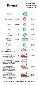


So the count would be 0.38x the square of the velocity that is 30x30x0.38= 342
From this account we would have to subtract the moment in which the angle of the blade causes suction and that the curve of the blade is not perpendicular to the wind all the time. So that drag effect could go down by 40-50% (that improvement is my assumption, it could be something more or something less).

Then we could assume that the drag coefficient is only 200 in that wind speed.

While the positive drag would be the product of the wind speed by the drag coefficient of that same semicircle: 1.42x the square of 16k/h= 363.
This is assuming that the blade is going to exert positive pressure in the turn from 0 to 180 degrees of turn, from less to more.

So the positive torque difference would be the product of 363- 200= 163.
That is what you can extract from drag difference: 60% being extremely positive in the calculations.

Probably the difference in torques is not so large, those calculations are thinking of the best of all worlds, and of the best two-blade savonius.

But I do these accounts simply to take as a basis for what I want to do now.

As seen in the second table, the drag coefficient of a teardrop profile is 0.04 drag, against 0.38 for a semicircular profile.

Achieving that exact profile in a normal savonius blade is not possible, because it would be more like a darrieus.

But the drag coefficient could be lowered by making a much more stylized blade curve, without reaching the extreme of the lenz design, which could take some advantage of the darrieus system, but loses almost all the drag that a savonius can generate in light and moderate winds (Until today I only saw one model of lenz working in very light winds, but without load, when not....).

For this reason and taking into account that I have to wait almost a month for the magnet samples to arrive and to be able to continue with the rotor tests, I decided to try a new blade shape for my savonius. At least in the small prototype. I already have the polypropylene plates and aluminum profiles that I had already bought for months in my last import, so the costs of testing this new design will be very modest.

According to my calculations, if I manage to lower the drag coefficient from 0.38 to 0.15 (very conservative considering that the tear has 0.04) I could do the drag multiplication in this way 0.15x the square of 30K/h = 135
And if I subtract 50% from that (as in the previous calculation) in concept of suction moment and the angles in which it does not face the wind at 90 degrees, it could reach 65 of drag, which would leave me a potential difference in torque of 300 instead the 163 in normal savonius shape of blades.

It would be twice what I get now from positive torque, the only drawback I find is that with the same amount of material for the blades, the total diameter decreases by 30%. So the swept area decreases a little bit.


This would be the new shape of the blades. And turning the drawing in corel, I think that almost at no time is the leading edge facing 100% perpendicular to the wind, because what I would expect is very low levels of drag.

If anyone has read this far (I already look like Adrian with the formulas  ;D) I ask them if they have already seen a turbine with a similar design and that at least works.

Maybe someone has already seen something like this, and it saves me from wasting time doing the blades like this to see if it improves performance.


[ Specified attachment is not available ] [ Specified attachment is not available ] [ Specified attachment is not available ]


« Last Edit: February 08, 2023, 01:58:06 PM by leviatan »

Adriaan Kragten

  • Hero Member
  • *****
  • Posts: 1158
  • Country: nl
Re: considerations about drag coeficients in savonius shape turbines
« Reply #1 on: February 08, 2023, 03:53:35 PM »
In my report KD 416, I describe a pure drag machine. I have used half hollow spheres because this geometry gives the largest difference in drag coefficient depending if the hollow or the convex side is fasing the wind. I have mounted two cups on a string which rotates around two wheels and have assumed that the wind direction in parallel to the strings. So one cup is moving in the direction of the wind and one cup is moving against it. If you look only at the cup which is moving in the direction of the wind, it can be proven that this cup must move with a speed of 1/3 * V to generate maximum power. However, the second cup will move against the wind and this makes that the relative speed of the wind with this second cup is 4/3 * V. Calculation shows that this second cup consumes all power generated by the first one even if it has a much lower drag coefficient. That is because the drag D increases with the square of the relative wind speed. For maximum power generation of both cups, the first cup must move with a much lower speed than 1/3 V. The maximum Cp of such a rotor is therefore very low.

This theory for a drag machine can't be used for a Savonius rotor as for a Savonius rotor there is a rather large flow through the rotor for the position of the rotor when the two buckets are about perpendicular to the wind direction. This flow creates not only lift on the bucket which is moving in the direction of the wind but also lift on the bucket which is moving against the wind direction. A requirement for a good flow is that there must be a sufficient large overlap in between the two buckets. The direction of this flow with respect to the rotor changes every half revolution and so there is a large part of a revolution for which the speed of the flow is low. During this part of the revolution, the rotor works as a drag machine.

If you use three buckets, the flow through one bucket is partly blocked by the other two buckets even if the three buckets don't touch each other in the centre. So a Savonius rotor with three buckets works more as a drag machine than a Savonius rotor with two buckets. Therefore it has a maximum Cp which is much lower than 0.24 which is the maximum value for a 2-phase Savonius rotor (with 2 * 2 buckets and three horizontal disks).

If you study my report KD 416, you will see that exact description of a drag machine, which is simplified such that the cups move in a straigh line, is rather complicated. Exact description of a drag machine for which the cups are rotating, is even more complicated and I would not know how to do it. I think that exact description of the generated torque of a Savonius rotor for every position of the rotor is impossible. So the only thing you can do is build one and test it in front of an open wind tunnel or on top of a truck.

Your lowest picture with very strongy curved blades allows no substantial flow through the rotor and therefore it is a pure drag machine with an inherent very low maximum Cp. Remember, wind will only flow from a high pressure to a low pressure. If you create too much resistance in the path the wind should take through the rotor, it simply won't take that path and it will prefer to flow around the rotor because for that path the resistance is less.
« Last Edit: February 08, 2023, 04:09:08 PM by Adriaan Kragten »

MagnetJuice

  • Hero Member
  • *****
  • Posts: 558
  • Country: ca
Re: considerations about drag coeficients in savonius shape turbines
« Reply #2 on: February 08, 2023, 04:06:48 PM »
Now you are delving into the unknown, where normal rules do not apply and the possibilities are endless.

By adjusting the blade profile and their position, you can end with a TSR between .8 and 3.8.

Then the question becomes:

Is it an H-Darrieus or is it a Savonius?

It is neither. It is a Darivonius.  ;)

Ed
What can I do TODAY that would make TOMORROW a better world?

Crockel

  • Jr. Member
  • **
  • Posts: 62
  • Country: ca
Re: considerations about drag coeficients in savonius shape turbines
« Reply #3 on: March 19, 2023, 06:52:51 PM »
I've been working on something similar. I made a spreadsheet to find lift and drag loads and moment on a savonius bucket blade (and torque about the rotational axis) as the blade moves 360 degrees around the shaft. I was hoping to use it to model the effect of varying the blade angle of incidence.

I have the drag coefficient at 90 and -90 degrees to the airflow (from this topic) but that's about it. I found a CFD app that I was able to model a very thin highly cambered airfoil in to get cL, cD and cM from -30 to 30 AoA. I even found 360 degree airfoil coefficient data for a typical Darrieus turbine airfoil blade but no data for my Savonius blade.

MattM

  • Hero Member
  • *****
  • Posts: 1178
  • Country: us
Re: considerations about drag coeficients in savonius shape turbines
« Reply #4 on: March 19, 2023, 09:25:29 PM »
Turn your buckets 90⁰, how does it impact the results?