Author Topic: How to determine the limits of a coil / magnet configuration  (Read 38001 times)

0 Members and 25 Guests are viewing this topic.

MattM

  • Hero Member
  • *****
  • Posts: 1178
  • Country: us
Re: How to determine the lmits of a coil / magnet configuration
« Reply #66 on: February 08, 2024, 07:18:12 AM »
Why face poles towards neighboring magnets?

Conventional righthand rules would be to face poles up and down rather than side to side.  Your current arrangement depends on side lobes of the magnet that maybe at most 30% the strength of the actual pole.  You are losing >40% of your magnetic influence.

brandnewb

  • Hero Member
  • *****
  • Posts: 694
Re: How to determine the lmits of a coil / magnet configuration
« Reply #67 on: February 08, 2024, 07:54:19 AM »
Yes Sir,

I have indeed also scheduled traditionally oriented magnets in the coming test sessions.

But the plan of attack makes sense to you or not?

brandnewb

  • Hero Member
  • *****
  • Posts: 694
Re: How to determine the lmits of a coil / magnet configuration
« Reply #68 on: February 08, 2024, 08:05:08 AM »
Why face poles towards neighboring magnets?

Ahh here we come full circle as to the why. And NO it is not because I just want to do something strange.

Nah. It all began with the fact that I bought these magnets on some kind of tradeoff between cost and power.

I bought 48 of them.

So that made me rather hellbent on this particular parameter.

I can admit if that is just silly. But I am not letting go just yet.

Anyway with these magnets being but 5mm thick I ran into issues with being able to create(3d print for me as machining is a bit out of my league yet) a holding disk strong enough to stay put.

So that is when I thought. hmm ok when I rotate them then I have more strength in terms of the holding disk as now it is 10mm rather than only 5mm.

Well that was the beginning of a whole lot of embarrassing history for me which can be found here.

But I am just plowing through. Just to make sure. I mean now I think I have gotten more understanding and means on how to actually demonstrate the effects of all of this.

And I will reiterate. Should repelling be indeed be a dead end then of course I will also share that.

Truth trumps pride after all.

And please lets not forget I indent to also test having coils on both sides of the single magnet rotor.

brandnewb

  • Hero Member
  • *****
  • Posts: 694
Re: How to determine the lmits of a coil / magnet configuration
« Reply #69 on: February 08, 2024, 09:17:11 AM »
to really make uit understood that I am not taking it lightly here is an example of coil variations.
And some magnet variations.
15829-0


all I care about at this stage is to get a consensus regarding if my battle plan is sound or not.

brandnewb

  • Hero Member
  • *****
  • Posts: 694
Re: How to determine the lmits of a coil / magnet configuration
« Reply #70 on: February 08, 2024, 10:00:35 AM »
that is to ask for an opinion or gut feeling one might have. Kind of like the poll I tried weeks ago that never went anywhere.

Please do not leave me hanging in limbo in where no one answers and then I have to go into a certain path based only on gut feeling.

I really need to be able to resist future naysayers from stating. Yeah but A. and B and blah blah blah.

Now is the time to shine!!!!!!

brandnewb

  • Hero Member
  • *****
  • Posts: 694
Re: How to determine the lmits of a coil / magnet configuration
« Reply #71 on: February 08, 2024, 10:37:17 AM »
btw proper scientific conduct must at all times allow for scrutiny and counter evidence at any time.

but i guess one knows what I meant.


Mary B

  • Administrator
  • SuperHero Member
  • *****
  • Posts: 3178
Re: How to determine the lmits of a coil / magnet configuration
« Reply #72 on: February 08, 2024, 11:15:52 AM »
Why face poles towards neighboring magnets?

Ahh here we come full circle as to the why. And NO it is not because I just want to do something strange.

Nah. It all began with the fact that I bought these magnets on some kind of tradeoff between cost and power.

I bought 48 of them.

So that made me rather hellbent on this particular parameter.

I can admit if that is just silly. But I am not letting go just yet.

Anyway with these magnets being but 5mm thick I ran into issues with being able to create(3d print for me as machining is a bit out of my league yet) a holding disk strong enough to stay put.

So that is when I thought. hmm ok when I rotate them then I have more strength in terms of the holding disk as now it is 10mm rather than only 5mm.

Well that was the beginning of a whole lot of embarrassing history for me which can be found here.

But I am just plowing through. Just to make sure. I mean now I think I have gotten more understanding and means on how to actually demonstrate the effects of all of this.

And I will reiterate. Should repelling be indeed be a dead end then of course I will also share that.

Truth trumps pride after all.

And please lets not forget I indent to also test having coils on both sides of the single magnet rotor.

There are MANY online machine shops who can laser cut steel magnet rotors for you, with that big of a rotor I would go to 3/8"(10mm) material and even at that you may need to gusset it to prevent flexing.

brandnewb

  • Hero Member
  • *****
  • Posts: 694
Re: How to determine the lmits of a coil / magnet configuration
« Reply #73 on: February 08, 2024, 01:42:10 PM »
Thx guys for the input.

Yet I feel we are diverting from the matter at hand.

Please focus solely and only on the matter at hand as outlined below;
 
1) create a bunch of different test coils varying from 0.4mm diam wire size to 1mm diam. and also in shape.

Do make sure that the 0.4mm wire coils are at all times 4 x more winds than the 1mm one. As one can fit only 4 times that wire in the same space of a 1mm one.

2) run various magnet configurations over all variations of the coils at the intended frequency. for single density that would be around 3.8 Hz and for double density that would be double that.

3) record what voltage each coil can produce at said frequencies,

4) hook up an Variable Frequency Drive to the variac at the intended frequency and at the voltage level it would have produced while induced by the magnets spinning.

5) now measure the magnetic field on each coil making sure to also take into account the depth and area it encompasses ( larger is better for breaking ability)


Now what I am looking for is either to hear "sounds like a plan" or "nah this is a bogus plan and I will tell you why"

JW

  • Development Manager
  • Super Hero Member Plus
  • *****
  • Posts: 4052
  • Country: us
    • Flashsteam.com
Re: How to determine the lmits of a coil / magnet configuration
« Reply #74 on: February 08, 2024, 02:21:14 PM »

 HAAA!

could you imagine this guy working on solid-state electronics. Then PC software etc.

 I'm sorry sir you bricked the Motherboard 

brandnewb

  • Hero Member
  • *****
  • Posts: 694
Re: How to determine the lmits of a coil / magnet configuration
« Reply #75 on: February 08, 2024, 02:40:31 PM »
Ahh yes, I do brick most things I touch.

However I am proud to share this insane threadripper I managed to build years ago and am working from at his very moment,

15830-0

I mean 128 x is not something to sneeze at is it?

Now JW I think you can help me become better and I kindly ask you for advice and guidance. Let us get this show on the road together ok?

JW

  • Development Manager
  • Super Hero Member Plus
  • *****
  • Posts: 4052
  • Country: us
    • Flashsteam.com
Re: How to determine the lmits of a coil / magnet configuration
« Reply #76 on: February 08, 2024, 03:34:16 PM »
Education isn't free. Look I built this website in a continuous process over 20 years.

You need to do some self study with the topics you are interested in. Its like you are speaking another language we cant understand you.


You gotta stop trying the most easy way, and this place isn't it. read book and understand info the so you can speak our language.

Quote from: brandnubee
Now JW I think you can help me become better and I kindly ask you for advice and guidance. Let us get this show on the road together ok?


brandnewb

  • Hero Member
  • *****
  • Posts: 694
Re: How to determine the lmits of a coil / magnet configuration
« Reply #78 on: February 08, 2024, 04:02:30 PM »
dear brother!

please refrain from sharing links with all kinds of tracking query strings attached to it.

I mean us brotherhood of programmers know better yes?

JW

  • Development Manager
  • Super Hero Member Plus
  • *****
  • Posts: 4052
  • Country: us
    • Flashsteam.com

MattM

  • Hero Member
  • *****
  • Posts: 1178
  • Country: us
Re: How to determine the lmits of a coil / magnet configuration
« Reply #80 on: February 08, 2024, 09:55:46 PM »
You could always go radial rather than axial.

brandnewb

  • Hero Member
  • *****
  • Posts: 694
Re: How to determine the lmits of a coil / magnet configuration
« Reply #81 on: February 09, 2024, 04:31:16 AM »
Yes sir understood.

I did buy a kindle of Mr Piggott rather early in the process though.
15831-0

But It must be that I am unable to search effectively as I was not able to find answers to my questions.

And believe you me I am self studying. Hard!!! I just operate a little slow and I have issues absorbing all information effectively, especially when higher math is involved. (not that I saw that in this kindle though)

And the trail and error process I am using to hopefully arrive at a great solution also is not without cost. But I will take those and hopefully end up with a rather limited bill of materials.

So I will just go on doing what it is I am doing and asking questions and sharing my progress. I hope it may benefit the world at some day in time.

Education isn't free. Look I built this website in a continuous process over 20 years.

You need to do some self study with the topics you are interested in. Its like you are speaking another language we cant understand you.


You gotta stop trying the most easy way, and this place isn't it. read book and understand info the so you can speak our language.

Quote from: brandnubee
Now JW I think you can help me become better and I kindly ask you for advice and guidance. Let us get this show on the road together ok?
   

Bruce S

  • Administrator
  • Super Hero Member Plus
  • *****
  • Posts: 5375
  • Country: us
  • USA
Re: How to determine the lmits of a coil / magnet configuration
« Reply #82 on: February 09, 2024, 08:35:51 AM »
You can also contact him via his website.
https://scoraigwind.co.uk/contact/

While he may not answer back as quick as some might like , he does answer most emailed questions.

Bruce S

A kind word often goes unsaid BUT never goes unheard

MattM

  • Hero Member
  • *****
  • Posts: 1178
  • Country: us
Re: How to determine the lmits of a coil / magnet configuration
« Reply #83 on: February 09, 2024, 09:27:45 PM »
I can vouch he does engage if you can stay focused on the question.

brandnewb

  • Hero Member
  • *****
  • Posts: 694
Re: How to determine the lmits of a coil / magnet configuration
« Reply #84 on: February 11, 2024, 10:13:30 AM »
yes of course not ;)

since it is still my believe that it is about the speed in the change of field then a sudden dip to 0 would only add to the the voltage.

We should not be trying to visualize the voltage graph in a direct relationship to the field.

Patience my young padawan. Patience. You will get there.

what I do not yet understand though is that I do not see this sudden dip to 0 that I was expecting in between opposing fields.

I am guessing that the electrons in the copper wires are able to also pick up on fields that are not ideally perpendicular.

brandnewb

  • Hero Member
  • *****
  • Posts: 694
Re: How to determine the lmits of a coil / magnet configuration
« Reply #85 on: February 11, 2024, 10:39:59 AM »
Ok now my insecure nature kicks in again.

Am I adviced to just leave as this place is not it? What ever that meant.

I rather just keep on plowing through and share what I find out along the way.

If nothing else it will be a great journey,

But I think we already see it coming yes? Something wonderful!

MattM

  • Hero Member
  • *****
  • Posts: 1178
  • Country: us
Re: How to determine the lmits of a coil / magnet configuration
« Reply #86 on: February 11, 2024, 12:31:31 PM »
By using the basics of Faraday's law you can see the inputs and then make some assumptions.

JW

  • Development Manager
  • Super Hero Member Plus
  • *****
  • Posts: 4052
  • Country: us
    • Flashsteam.com

brandnewb

  • Hero Member
  • *****
  • Posts: 694
Re: How to determine the lmits of a coil / magnet configuration
« Reply #88 on: February 12, 2024, 07:56:40 AM »
I think that when orienting magnets traditionally then it be important not too close. I think a lot of the field is not going through the coils but is diverted in between adjacent magnets.

Well that is what I will be testing next. To see if repelling without back plating (back plating in a repelling setup only hurts the field rather than benefit it)

But even so traditional with but a 15mm spacing between rotors already packs a punch. A hard one at that!

Look how crazy.
15837-0
15838-1
1.76 VAC at 3.6 Hz if I interpret the readings correctly. Now I would like to know if this is impressive or not.

{1}
So here the coils are 200 winds very narrowly wound @ 0.4mm diam wires.
They are not stacked yet spaced in such a manner to roughly end up with a 3 phase shift between them.
The reasoning (but open to debate as per usual) behind this configuration is that the heat dissipation ability can be more easily achieved than with while stacking coils.

And also regarding stacking coils, I still fear that the magnetic fields induced will suffer from interference. This phenomena one can see with waves.
But then again I first need to see that it in order to believe it ;)

{1}

{2}
Also I am worried that once the coils start behaving like electromagnets (as is the intend after all to actually produce power) then the magnets on the rotors might become persuaded to let go of the back plating :( Not at all something one looks forward to when a PMA is in operation.
{2}
« Last Edit: February 12, 2024, 08:18:07 AM by brandnewb »

brandnewb

  • Hero Member
  • *****
  • Posts: 694
Re: How to determine the lmits of a coil / magnet configuration
« Reply #89 on: February 12, 2024, 08:33:07 AM »
So repelling at 3.75 degree interval on a 2 rotor setup does less than half as what traditional does in similar enough circumstances.

This is not looking good for that setup.

I will try now doubling the density. See if doubling the Hz will do something for this super narrow coils (after all they were wound that way for this specific scenario)
« Last Edit: February 12, 2024, 09:22:00 AM by brandnewb »

brandnewb

  • Hero Member
  • *****
  • Posts: 694
Re: How to determine the lmits of a coil / magnet configuration
« Reply #90 on: February 12, 2024, 11:56:35 AM »
yeah no, there is just no way yet I can demonstrate repelling to be generating more voltage than traditional in this dual rotor setup.
Not even when going double density.

And yes sure I am comparing apples to oranges making things rather hard to take seriously. Even for me the one designing and running the experiments.

But it ain't over till the fat lady sings yes?

Just do not hold you breath. I certainly no longer am not. But I just need to see so I can close the pages on this matter once and for all.

JW

  • Development Manager
  • Super Hero Member Plus
  • *****
  • Posts: 4052
  • Country: us
    • Flashsteam.com
Re: How to determine the lmits of a coil / magnet configuration
« Reply #91 on: February 12, 2024, 12:41:34 PM »
Man your really into theory.

Most of us are into Proactive " proactive/practical application"

Carry on

MattM

  • Hero Member
  • *****
  • Posts: 1178
  • Country: us
Re: How to determine the lmits of a coil / magnet configuration
« Reply #92 on: February 12, 2024, 02:12:15 PM »
With magnetism the force lines are always uniform.

If they are not then another influence is present.

MagnetJuice

  • Hero Member
  • *****
  • Posts: 558
  • Country: ca
Re: How to determine the lmits of a coil / magnet configuration
« Reply #93 on: February 13, 2024, 12:23:59 AM »
Hi brandnewb,

After your many requests for help, I'll agree to help you with the design of the alternator for your Phoenix VAWT.

I have read many of the posts on the diysolarforum, where you started your journey to build the 'sickest VAWT' over 2 years ago.

From the beginning, there were some users there and on this Forum that gave you good and sound advice. It is possible that you could not grasp what they were telling you. That is probably why you chose to continue to do it your way, even without a clear understanding of some of the simplest electrical terms and without an understanding of electromagnetism. It takes time and a lot of effort to learn that stuff.

At least you have perseverance and enthusiasm, that is good and commendable, but as I told you in the IM's, it will only help you if you have goals and stay focused.

I don't know how successful I will be in getting you back on the road, but I am going to give it a shot.

You have said many times that you want to do some tests that will help this Forum. So I am going to suggest some useful tests that you can do that will be helpful to us here and will help you acquire good data for your future BIG alternator.

I will start with this statement; you cannot get useful data by doing tests with the coils and magnets that you are using now, and I'll tell you why.

The magnets that you are using are too small and they have the wrong proportions of length to width, and they are too thin. Nobody will ever seriously think about using magnets like that to build an alternator. So, any tests that you do with those magnets are not useful when it comes to building an alternator.

When you asked about stacking magnets, Adriaan wrote this:

"However, if the total magnet thickness is about the same as the total air gap thickness, you can better keep it as it is"

I think that you missed that. What Adriaan said is that the ideal air gap for your 5mm thick magnets is 5mm. The 3 overlapping coils that you have are about 30mm thick? At 30mm, the flux reaching the coil will be less than 15%. You need thicker and wider magnets.

The coils that you are using now are useless for any type of alternator. The wire is too thin and with too many turns. That makes the resistance way too high.

This equation, P = (I^2) x R is used to find the power dissipated by a resistor in watts.

Remember this, when you build an alternator and you wire all the coils, the finished alternator becomes a large resistor.

Most of the alternators that are built by some of the members here have coils with resistance of .5 ohms or less. The resistance of your coils is about 9 ohms per coil.

P = (I^2) x R
P = power in Watts
I= Current in Amps
R= Resistance in Ohms

Example:

If resistance of one coil is .5 ohms, 3 coils in series is 1.5 ohms.

Assume that the current is 15 amps and voltage is 58 volts.

Total alternator power = 870 watts

P=(15x15) x 1.5 = 337 watts dissipated as heat in the stator.

Now let’s see how much power will be dissipated with 3 of your 9 ohms coils.

P=(15x15) x 27 = 6,075 watts (HEAT) dissipated in the stator.

That will not be called an alternator. It will be a copper smelter.

The bottom line, you need to keep coil resistance at .5 ohms or less.

The only way to do that is to use less turns and use at least 1mm wire for the coils.

If you can build a good testing platform with 2 rotors similar to this, it will help a lot:
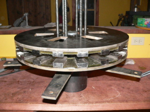


It doesn’t have to be that big, 8 or 12 magnets per rotor should be OK.

You already have a Variable Frequency Drive. All you would need is a 2 HP 3-phase electric motor for turning the rotors at different speeds. Or you can use your Variac to turn a DC motor. The DC motor might be a better choice because the VFD's have a hard time running at very low RPM.

With that setup you can test different coils with different air gaps at different speeds and do other tests to get useful data that could also be of value to Forum members.

If you are interested in building the testing platform, let me know and I can help you with that.

Don't expect to get an electrical or electromagnetism education from Forums. We all learn mostly by doing and building things.

When you can sit in your warm home and look out the window and see the Phoenix spinning and making watts, then you will notice that you have learned quite a lot. And if you stay focused, that could be soon.

Ed
What can I do TODAY that would make TOMORROW a better world?

brandnewb

  • Hero Member
  • *****
  • Posts: 694
Re: How to determine the lmits of a coil / magnet configuration
« Reply #94 on: February 13, 2024, 03:10:50 AM »
Thank you Ed,

This means the world to me!

So I have been able to figure out where that image came from or at least determine that it is also used by a Vietnamese seller of PMA kits.
https://www.blogdiengio.com/p/nhan-lam-bo-kit-may-phat-ien-500w-1kw.html

here is a translation of what is written in the context of that image
"Get generator kits for 500w, 1kw, 2kw, 3kw, 5kw

Do you want to make your own generator but don't have time or are you simply lazy? Let us help you. The machines we make are close to the capacity and suitable for where you live. Please contact Lam Nguyen"

My complaint to sellers like this and to the endless videos being shared online that they always fail to mention how it was determined to have a certain rating.
That was the origin of my question to you in the PM magnets to watts.
Let alone it says nothing about the coil shape and the reasoning behind that coil shape.

And of course I trust you and I will listen to you and will set this up I just fear the RPM need to be really high in order for the voltage produced to be of any use.
But as you stated I do lack a lot of understanding yet so let us just go at it and see where this leads us.

So step 1 would be is to eyeball the dimensions of this setup yes?
I am having difficulties guessing as I do not see a clear reference point to work from.
Step 2 would be sourcing these type of magnets. And I can I have already checked.
https://www.supermagnete.nl/blokmagneten-neodymium/blokmagneet-40mm-40mm-20mm_Q-40-40-20-N
if we opt for a 60kg holding force

or we can go a little stronger with something like this
https://www.supermagnete.nl/blokmagneten-neodymium/blokmagneet-50.8mm-50.8mm-25.4mm_Q-51-51-25-N

Now obviously the relationship between cost and power is lost but that does not matter in the pursuit of science.

brandnewb

  • Hero Member
  • *****
  • Posts: 694
Re: How to determine the lmits of a coil / magnet configuration
« Reply #95 on: February 13, 2024, 04:02:45 AM »
in the meantime I have already a tentative conclusion that indeed a 1mm wire is the way forward as opposed to smaller.

What I did is have a coil of 1mm wire with 10 winds and a coil of 0.4mm wire at 40 winds.

Coil shape was narrow like in the double density tests.

When at around 8 Hz the 0.4 coil did around 160mV and the 1mm coil did around 48mV.

Then I hooked up each coil separately to the CVCC and fed in the voltage level they produced at 8Hz.

Then I measured the field strength at 10mm distance on both.

The 1mm coil had 16mT and the 0.4 coil had 8mT.

Unless I am tackling this wrong I think we have a clear winner {1}for when winding narrow.

But in the process just now of trying a coil shape that is matched to the magnets at 3.75 interval then this happened.

15841-0

at 3.8 Hz the 10 winds 1mm coil did around 100mV and the 40 winds 0.4 coil did around 410 mV.
at 100Mv DC the 10 winds 1mm coil produces a field of 25mT in the center at 10mm distance. the field drops sharply when moving to the coil legs.

at 410mV DC the 40 winds 0.4 coil also produced a field of 25mT in the center at 10mm distance. the field drops sharply when moving to the coil legs.


Now I think it is a matter of finding the sweet spot of how thick we can get wires. 1mm might indeed be the absolute minimum.


{/1}

{2}this website actually does tell a lot about the coil and shape. so something to hold on to and work from in terms of dimensional reference point.{/2}
{3}albeit that the coils seem to vary from picture to picture. So I am not sure which one was intended for the rotor configuration and which KW rating was attributed to it.{/3}


« Last Edit: February 13, 2024, 06:26:38 AM by brandnewb »

brandnewb

  • Hero Member
  • *****
  • Posts: 694
Re: How to determine the lmits of a coil / magnet configuration
« Reply #96 on: February 13, 2024, 09:25:28 AM »
So I arrive at a diameter of around 500mm for the disks used in that example.

I am looking for 2 steel disks of that diameter with a thickness of 10mm.

I can purchase as well as the magnets. I can make it similar enough to the example and am eager to do so.

Yet before I proceed. Are we sure the design goal of low RPM will be met? If I look at one of the photos on that website you can see a clear motion blur indicating the disk is spinning far faster than I would like my disk to spin at.

brandnewb

  • Hero Member
  • *****
  • Posts: 694
Re: How to determine the lmits of a coil / magnet configuration
« Reply #97 on: February 13, 2024, 10:09:58 AM »
Please warn me ahead of time if this is getting out of bounds and I should be less loud.

Yet while waiting on a consensus if this Vietnam idea can serve as a good baseline I am staying focused on the actual topic of this thread!

So I have already ordered 1.5mm wire and 2mm wire. It will be here in a few days.

We will no longer be using anything smaller than 1mm wires from now on unless new evidence is brought up that warrants scrutiny.

Also I went to the other end of the spectrum with coil winding and went with a single wire (1mm) serpentine in a double density setup.

15844-0

Here I find that at around the intended Hz for double density 7.6Hz this 5 coil serpentine can do a little less than 20mV.
And when that serpentine is subjected to 20mVDC then the field that can be measured between each wire at a distance of 10mm is around 4mT.

[ Specified attachment is not available ]

I am beyond confused though to find that the last coil leg, at 10mm distance showed a 9mT reading.


brandnewb

  • Hero Member
  • *****
  • Posts: 694
Re: How to determine the lmits of a coil / magnet configuration
« Reply #98 on: February 13, 2024, 11:17:57 AM »
Unless again making a huge blunder again I think I just witnessed interference being a problem.

15846-0
15847-1

So this for me means a clear sign of why not to go close with coils and even try to stack them.

well it is good to find out this early in the process.

But now the whole coging monster is just waiting to rear its ugly head again if we start spacing coils.