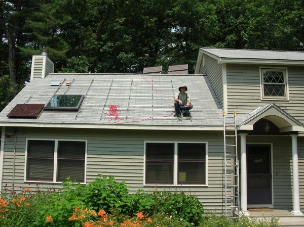
My solar panel project, phase 2, has gotten to the point where it might be of interest to others. (Phase 1 was just a few panels for emergency power use, which you'll see better in a picture below.) In this phase, 20 60w Kenaka thin-film panels are being flush-attached to part of our roof. (All in parallel as these are being fed into an MX60 and then to a GVFX3648 and even putting them in serial-pairs would exceed the max input voltage of the MX60.) This first picture is a view of the entire work area showing the support bars in place and one panel attached as a test:

What you can't really see in this picture is that the rope that is coming down to your's truly is attached to a full body harness. This section of roof is at a 45 degree angle and there is no way I'd work on it without a safety rope. (Especially in the corner by the first panel where a foot in one direction leads to the driveway over two stories down, one foot at a diagonal lands me in the feed wires to the house, and one foot towards the camera is a one story drop to the ground. Too bad that has to be the first panel to go in.)
As mentioned above, 20 panels will be going in. There are four rows of five panels in each; two rows of which are interrupted by the skylight and two rows that will be higher on the roof than the skylight. In the two lower rows, there will be one panel to the left of the skylight and four to the right. The upper rows will start just slightly to the left of the skylight and will have five panels in a row. Looking at the right side of the roof, note how the upper two rows end further to the left than the bottom two rows do. The early morning shadow from the house part on the right impacts the upper rows more than the bottom ones, so this "shift-left" in the upper two rows minimizes any shadow impact.
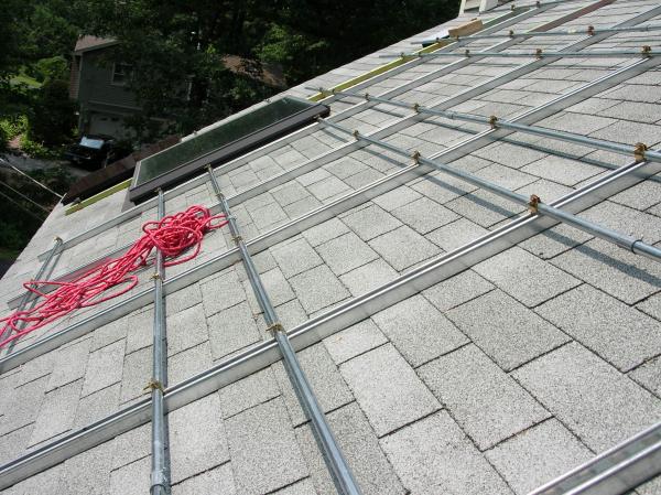
In this next shot, you can get a better feel for the pitch of the roof (look at the house in the distance and you'll see that I wasn't holding the camera level) and see what I'm using for the support bars.

The vertical pieces (referring to their orientation on the roof, not in this picture) are "Superstruts" which are U-shaped channels with lips along the edges that their pipe clamps grab onto. The horizontal pipes are 3/4 inch EMT piping. This gives nice flexibility in the horizontal placement of the panels, but there is one "gotcha" that I had to be aware of: the pipe clamps. The upper part of the pipe clamp sticks up and the panels go over top of them with plenty of clearance. However, the edge of the panels - which have to be down by the EMT pipe to be attached - can't be in line with the pipe clamps. So, lots of measurements taken and planning on exactly where the rows of panels will start so that no edge of a panel comes too close to a pipe clamp. Ditto with the placement of the EMT connectors: I sized the right and left sides of the horizontal runs so that the connectors would not be right under the edge of any panels.
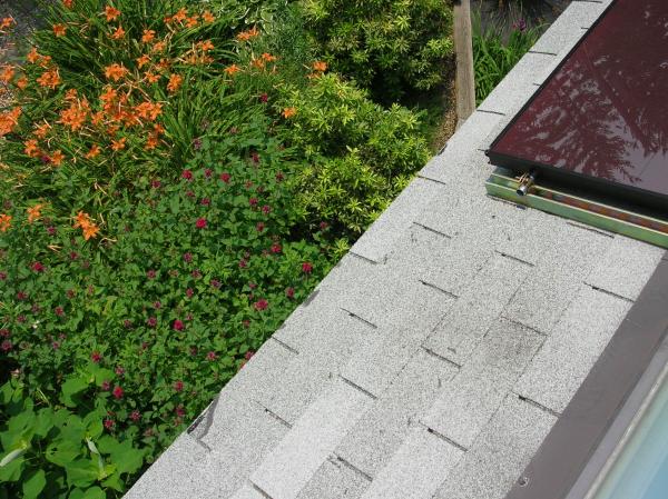
This next shot gives you a sense of the view from the "killer corner" (as I call it ;-) and shows the one panel that has been connected.

If you look real close, you'll see that there isn't much room between the roof surface and the bottom of the panel edges. The gap between the roof surface and the body of the panel is about 3.5 inches so the air will flow well, but when I was planning it I forgot that the gap at the edge of the panel, where my hands have to do the attachment work, is about an inch less. Ouch. In hindsight, I'd use a bigger gap to make the installation go easier. (And speaking of the 3.5 inch gap, I'm toying with the idea of installing spritzing hoses in this gap given the results of the other poster's test (sorry, forget his name right now) showing the improvements of keeping the panels cooler.)
Now, a humorous story about this plants. The dark red flowers (those to the left of the picture's center and between the day lillies and the house) are monarda. This plant is noted for attracting hummingbirds, among other things, and we do see a few each summer. Well, yesterday I was working right where I took this picture at and looked down to see a hummingbird sipping nector! Besides being the best view I've had of a hummingbird in a long time, there was a funny moment when the hummingbird twice turned 45 degrees sideways and upwards and watched me for about 10 seconds each time. He (she?) was probably as curious, or at least weary, of seeing me "up there" as I was happy at seeing the bird down below!
Anyone, one last picture for now. I mentioned that these panels are phase 2 and that phase 1 was a few panels for emergency power. Well, here they are:

More than just normally being for emergency power (portable microwave, rechargeable lights, etc.), I've decided to have some fun and just ignore the grid for this work. Any part of phase 2 that needs power, such as drilling the pilot holes for the roof lag screws, cutting supports, soldering wires, etc., will get its power from these little panels.
By the way, looking beyond these panels you'll see why I've mentioned in other comments that I have a few too many trees to install a windmill. :-(
I'll add updates as the work progresses.
Craig