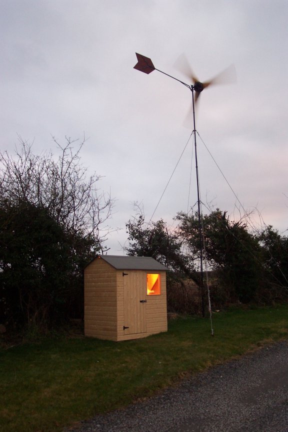
I have just got my Ghurd dump load controller working (in experimental mode) and thought I would share a little. My system is coming along painfully slowly but it is moving in the right direction. As the wind turbine is around 50m from the house I felt it was too far to bring low voltage. I also was too scared of the Boss to even suggest putting the battery bank in the house so I built a little shed at the bottom of the tower. In this pic I have a 500W halogen light powered from my 1400W UPS.
I have around 190Ah @24V of a battery bank, I know this is too small for my system but It is a start, I hope to upgrade it soon. The pic below shows some of the batteries I am using, They all came from old computer UPS's. You can also see the rectifiers screwed to a heatsink
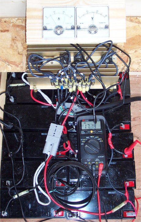
The wind was pretty light that day, the ammeter is on the left showing 5A and the voltmeter is showing 17.2V. When I found the batteries they were very low (around 6V) but seem to have come up quite well. The most power I have seen is >30A at >30V, I don't know the exact current as the meter was off the scale but I think I was seeing near 1KW. As this is a DanB Volvo brake disk 10 footer I guess I am doing well, maybe too well so I will be careful with it and first opportunity I will lighten the tail to let it furl earlier.
As the batteries charged I repeatedly saw voltages of 30V or more so I decided to get Ghurds little dump load controller going and the pic below shows how I connected it up.
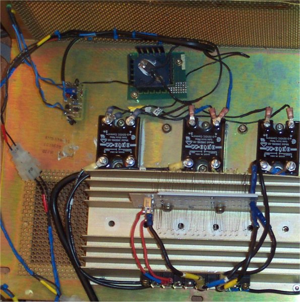
Glen connects his dump load onto the batteries but it was originally designed to handle 300W-600W and as I was seeing over 900W I decided to try something a little different. I also had a bunch of 45A ac solid state relays I got from some old computer mainframe kit which I was bursting to use. The pic above shows Glen's controller top left, the power FET top middle, then the three solid state relays and you can just see a portion of electric heater wire. When the controller triggers the FET switches 28.8V onto the solid state relays which then connects three lengths of heater wire across the three phases from the alternator. I didn't want to put too severe a load on the turbine so decided 300W was about right, I worked out what the resistance should be as follows.
When I saw approx 30Vdc I measured the ac voltage across 1 phase at approx 25V
I figured that if I dumped around 300W (100W per phase) I would need approx 4Ω across each phase. More by luck than skill I decided to cut the wire at 6Ω thinking I might change my mind. It was only when I had the wire connected and found it metered at 4Ω I realised by connecting them across each phase each resister wire was in parallel with the other two (in series) so each phase saw 4Ω almost exactly.
The pic below shows how it is all connected at the moment
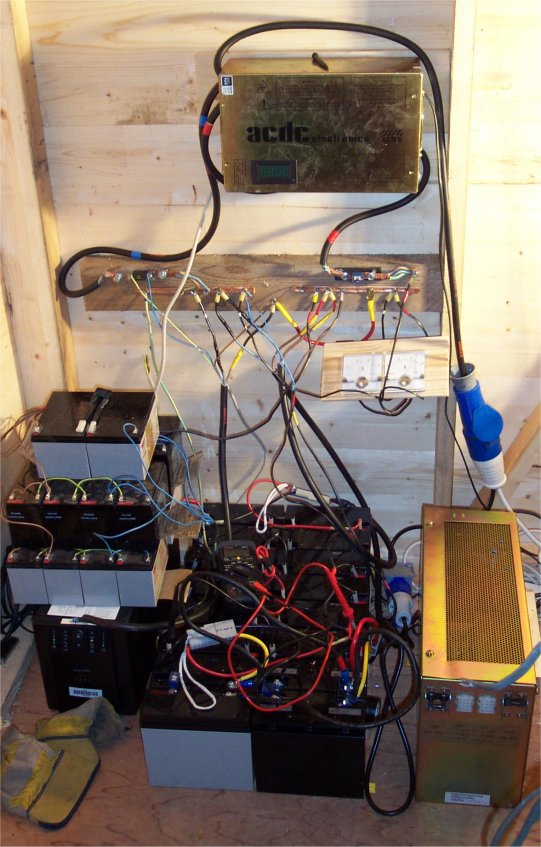
The box with acdc also came from old computer equipment so I thought it would be fun to put the rectifiers in it. I cut a hole and fitted a LED voltmeter/ammeter but I am not happy with it as the voltmeter seems to jump around a lot for no reason. I got some 10mm copper pipe, hammered it flat and folded it over to use as busbars. All the connections are held with woodscrews, screwed through it into the wood behind.
The 32A commando connector comes direct from the turbine so there is no concern about water getting in. So far I haven't had to untwist it. I also have another socket coming from the same cable which I can plug the brake into (a plug with three leads shorted). The box on the right has the dump load and you can just see the two led's at the far end of it. The gray cable in the foreground was just hanging up and got in the pic.
We had nice wind yesterday so I connected everything and let it go. The batteries came up to float voltage after a few hours and as I watched I could see the controller triggering every half second or so. I could feel heat from the resistance wire and the ammeter jumped up and down by at least 5-10 amps. I haven't done the maths yet but I guess it was dumping up to 250W.
As I said before this was an experiment and I can now see a couple of reasons for not putting the dump load across the ac side.
- As the ammeter is jumping up and down it is hard to see what the turbine is putting out.
- Ghurd says it is hard on the turbine. In my case the turbine seemed to continue spinning more or less at the same speed the whole time with only a slight change in the sound but Glen has much more experience than me so I will not argue with him
- As the dump load is not directly connected to the batteries I think it did not pull the voltage down as well as it would otherwise. This meant that even though the wind was not severe I saw the voltage rising above 29V.
Most of the work I did on connecting the controller is not wasted as I can use the same part of the heater wired slightly differently to put 6Ω or less (I will probably connect it for around 4Ω). I will need to connect a few more power fet's but it shouldn't be too hard. I will then build a second dump load controller and set it to dump at a slightly higher voltage.
Seeing it work was a lot of fun and feeling the heat generated by the product of ones own labours gave me quite a kick too.
A big thank you to Ghurd for help and advice with his little circuit
