I got a small CNC mill a while back, and finally got around to playing with it to make a small blade. I was aiming to make a blade for a 2 foot diameter prop as the mill has only 12 inches of travel in the X axis. This posting shows the results of the first attempt.
I don't have any good CAD/CAM software to work with, so I basically guessed a foil based on a modified NACA 4412 design, and designed it for a five degree angle at the tip and as much twist as I could get at the root. I created a plot of the airfoil at the root and the tip. Then I calculated a few lines from the root to the tip at various key points around the perimeter and used a spread sheet to plot lines that intersected with those lines at each X position. The outputs of those lines were then transformed via a report in Microsoft Access to a text file in G-Code format. Those files for the front and back of the blade are here. I modified those files to leave a couple of 'pillars' of material at two points along the X axis to act as supports because I was worried that the material might not be held securely in the vise if I removed all of the wood all of the way down. Here are the files for the front and back of the blade if anyone wants to see them.
FRONT: http://www.otherpower.com/images/scimages/742/20050221BLADEFRONT.txt
BACK: http://www.otherpower.com/images/scimages/742/20050221BLADEBACK.TXT
These files were from my main computer, and I think I made some minor changes to them when I actually put them on the computer attached to the CNC mill.
I loaded the program for the front, chocked in the material and homed the machine. Then I started the program.
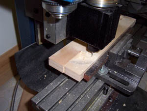
It started cutting and here it as it just finished cutting the root of the blade. I kept a vacuum handy as it created quite a pile of sawdust.
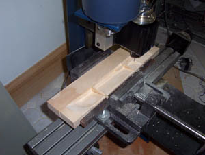
Here the machine is finishing the front of the blade. You can see the two 'pillars', or blocks of material that I left to act as supports.
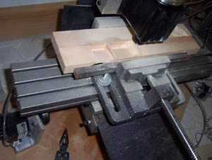
After the front side was finished, I flipped the block of wood over in the vise, homed the machine and ran the program for the back side.
All done with the back side, It took quite a while for this to finish a blade. The code could use some optimization, to eliminate some cuts that don't need to be made, and to speed up the cutting on shallower cuts.
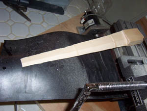
Here is the blade out of the machine. I will have some changes to make. The trailing edge was nearly paper thin. I will have to make the blade thicker. Also, I will need to smooth the root into the blade, I'll probably plot another set of lines from about 5/8" to the first profile on the root which was at 2.125 inches on this prototype, and then construct cuts for the positions along the X axis to smooth the transition from the block to the airfoil profile.
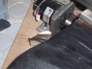
Here is an image showing the tip profile and it kind of gives you an idea of the twist. The twist is distributed linearly from the root to the tip. I'm not sure if that is ideal, but it is probably good enough, and it was the most simple way I could think of to do it.
For the next trial, I think I will change the profile to make the blade thicker. It seems very fragile as it is. I may also use a wider block of wood than the 1" by 2" (actually 1.5" by .75") used for this trial. I originally used the 1 by 2's as I could potentially mount three of them on a rack attached to a rotary axis I have on the mill and have enough clearance to flip all three. That way, I could load three blanks, let the machine run, and have three blades waiting when I returned. With wider wood that wouldn't be possible. The blades appear rather narrow to me and off the top of my head, I think they may have trouble at startup. I may, however, make two more blades identical to the first, just to play with them and see if they work. I have a bunch of small NEMA 17 stepper motors, and although I am not certain of the power rating for them, these blades might be a reasonable match.
I'll be out of town till Thursday, and I'll have a pile of work when I get back, so it will be next week at the earliest before I can play with these again. Rich Hagen