Although the are 3 phase it is imposable for the voltage of all 3 phases to be at there peak potential at the same time.
Dan B has stated he like the fact that all coils have current flowing through at all times. This is true.
An example of this is phase 1 is at zero potential at some point in its output do to rotor rotation. At this same point in time phase 2 and 3 are at 120 degrees either aproaching there peak output or leaving there peak output. This means voltage has to pass through phase 1 and at that instant phase 1 is just a coil in the way for current to pass on its way to the doides its connected to.
As a mater of fact the only way any of the ac voltage can reach a fullwave bridge is
to pass its current through a coil that is partialy an inductor only, or has current that is slightly in opsistion.
Puting littel inductors in sires with each phase is not a benifit. For those how understand phaseing try this wire your speaker out of phase in your audio system to see what happens to the acoutic energy.
If we could stop the alt intantly a measure what was happening at that instant we could acctuly see a DC voltage. At one end of a coil a positive voltage would be present and at the end of that coil there would be the negative. This alternates with the alternating magnetic flux but lets do that freez frame thing and check the relationship between phases at that nano second.
We would see that while one phase is producing it peak volktage the phase next to it would be produceing less. They can't all be on top of the hill at the same time. They are a manditory 120 degrees apart.
Its like wireing two 12 volt batteries in sires. Every time you tried to connect the 2 batteries one would instantly drop to 10 volts. You could never get the to be 12 volts at the same time. So you get 22 volts not 24 volts.
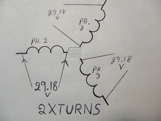
My proposal is to make each phase have 2 times the voltage as one phase. This solves the lost voltage isue. Then provide each phase with its own fullwave bridge rectifier. This keeps the voltage high (no phase to phase lose) The perelelling of the lower amperage higher voltage will provide the same amperage as the lower voltage higher amperage phases wire in sires.
A single phase example. A power transnformer will help to understand this aspect.
Lets say I have 2 transformers. They both have 120 primaries.
One has 2 sendaries at 10 volts 5 amps. If I wire these secondaries in perelell I get 10 volts 10 amps.
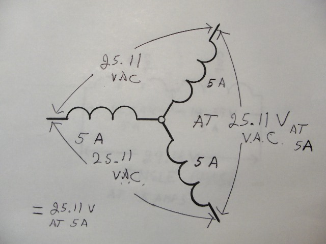
The other transformer has 2 secondaries at 5 volts 10 amps. If I wire these secondairies in sires I get 10 volts at 10 amps. This example is equal to star with one big exception I can never get 5 volts at the same time from the 3 phases or coil groups.
By wireing a seperate bridge to each phase a phase will never have to send its power through another phase that is not in total agreement.
Time for a couple more pix. Proposed coil change ans stock coil preformance.
Time to brake.
JK TAS Jerry
