Author Topic: and so it begins.....  (Read 8441 times)

0 Members and 1 Guest are viewing this topic.

charged

  • Newbie
  • *
  • Posts: 40
and so it begins.....
« on: January 15, 2004, 08:34:51 AM »
I'll be putting some useful circuits and maybe some weird pics here soon. But, don't hold your breath until then....

« Last Edit: January 15, 2004, 08:34:51 AM by (unknown) »

JW

  • Development Manager
  • Super Hero Member Plus
  • *****
  • Posts: 4051
  • Country: us
    • Flashsteam.com
Re: and so it begins.....
« Reply #1 on: January 17, 2004, 10:23:01 AM »
Right On Charged,


 I have read your posts and postings with much interest. Your schmatics will be of great value to us all.


-JW

« Last Edit: January 17, 2004, 10:23:01 AM by JW »

wooferhound

  • SuperHero Member
  • ******
  • Posts: 2288
  • Country: us
  • Huntsville Alabama U.S.A.
    • Woofer Hound Sound & Lighting Rentals
Re: and so it begins.....
« Reply #2 on: January 17, 2004, 02:23:22 PM »
I would like to see a schematic of the Capaciter Pulse charging Curcuit all the way from the coils to the batteries and including the dumpload ?
« Last Edit: January 17, 2004, 02:23:22 PM by wooferhound »

monte350c

  • Full Member
  • ***
  • Posts: 228
Re: and so it begins.....
« Reply #3 on: January 17, 2004, 10:29:46 PM »
Hi Charged,


Congrats on the new diary! This could be a very interesting place to visit...


Hope you don't mind me posting this here - a while back I was asking all sorts of questions about Bedini motors, pulse charging etc.


I finally got down to business yesterday and made up the start to a Bedini motor. So far I have the motor part working quite nicely.


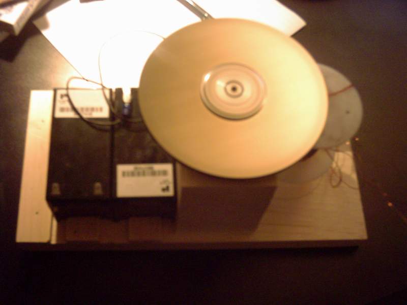
I started with an old Quantum Bigfoot hard drive - it contained a nice pair of 5" diameter aluminum platters. The hard drive's motor contains a set of really nice bearings that seem to have very little drag.


The two plates are about 1 / 4" apart, so I drilled 3 holes at 120 degree spacing in the bottom plate near the outside edge the same diameter as the magnets I had 'in stock'. Then I super glued the magnets to the top platter. The bottom platter's holes surround the magnets so they can't fly out.


Next I built up a wood 'chassis' to hold the rotor. The coil I wound with a tri filar winding out of 24 AWG wire. Due to some miscalculation on my part the coil only has 420 windings (oops!).


I tried a circuit first with some transistors I had in the parts bin. One made some smoke, and another almost ran the motor. In the end I broke down and got one of those TIP3055 (actually it's a MJE3055T) transistors, and a 10K multi-turn pot.


I set up the combined base resistance to about 360 ohms and hooked the battery up. (I'm using 2 1.3 amp hour 12 volt units) One spin and the motor was running.


As near as I can make out it's doing about 1900 rpm and using around 180 ma from the primary battery.


Next up - a 555 timer circuit to dump a cap into the secondary battery. Boy this if fun!!!


Here's a pic of the unit as yet unfinished. There's a set of screws around the inner flange area which are blurred because it's spinning!:


Thanks for all your help, I'll post more when the secondary circuit with the timer and caps is done.


Ted.

« Last Edit: January 17, 2004, 10:29:46 PM by monte350c »

monte350c

  • Full Member
  • ***
  • Posts: 228
Re: and so it begins.....
« Reply #4 on: January 17, 2004, 10:41:46 PM »
Here are a couple of links to our previous discussions:


Your original post on Bedini technology:


http://www.fieldlines.com/story/2003/11/12/8365/3048


One set of questions I had about Bedini stuff:


http://www.fieldlines.com/story/2003/12/14/234949/41


And another about wind turbines and pulse charging batteries:


http://www.fieldlines.com/story/2004/1/11/22449/4518


some stuff about off-beat alternators:


http://www.fieldlines.com/story/2003/11/25/202715/52


I know you have been a big help to me, it would be great to concentrate all the advice in one spot. Since you've started this diary - "Let the good times roll!"


Ted.

« Last Edit: January 17, 2004, 10:41:46 PM by monte350c »

RobC

  • Full Member
  • ***
  • Posts: 180
Re: and so it begins.....
« Reply #5 on: January 18, 2004, 08:59:05 AM »
Good job Ted I really like to see actual hardware in action. Maybe some body here will actually be able to duplicate John results. One more thing I have to say is thanks Charged for all your informative suggestions. I hope we can actually see John Bedinni claims proven I have been interrested in his motors and ideas for years. Maybe we will also see some of it applied to windmill generators.

RobC
« Last Edit: January 18, 2004, 08:59:05 AM by RobC »

SteveM

  • Newbie
  • *
  • Posts: 1
Re: and so it begins.....
« Reply #6 on: January 18, 2004, 08:24:54 PM »
Charged:


I think the creativity and links are great, will continue to follow.  I have been puzzling over a thought, hope you can shed some light.


Can the pulse charging circuit be used to control windmill output?  


I have been wondering if a continuously balanced blade and generator set operating in a range of wind speeds could improve the overall efficiency of a generator.


I was trying to keep it simple to visualize the problem.  Lets say the generator and blades are sized for average wind (11 MPH).  If the wind is less, the generator is spinning too slow.  If the wind speed is higher, the blades are spinning to fast.  In either event, energy is loss from improper blade generator matching.  


Now, I am not sure of all of the derivatives of this concept but the gist is simple.  An unloaded generator spinns freely, a loaded generator more slowly. I was thinking that if a pulse could vary either in amount of energy or speed of pulse it could be used to balance the generator load in various wind speeds.  In low wind speed conditions the pulse circuit stays unengaged to allow for easy startup (Free-wheel). Once their is enough energy or voltage to pulse the circuit does so. If the winds pick-up and the voltage on the capasitor side increases can the pulse speed increase as well?  I was thinking along the lines, that when more energy is available from the blade, the load on the generator is incrementally increased to provide a balanced match along the wind velocity curve.


Food for thought.


Love the work.


Steve M

« Last Edit: January 18, 2004, 08:24:54 PM by SteveM »

charged

  • Newbie
  • *
  • Posts: 40
Re: and so it begins.....
« Reply #7 on: January 26, 2004, 12:26:35 PM »
The simplest solution is to build a capacitor flip-flop power transfer directly into the generator using solid-state switching. Starting from scratch, build a single-phase generator with gaps between the stator windings so that the output waveform is small AC wave pulses separated by a zero-current period, little bursts of AC.


Rectify those with a single diode into a large capacitor.


Then, offload that capacitor during the zero-current periods between bursts. This means you only need one solid-state pulse switch and a hall-effect device to time the pulses. Just mount a tiny neo magnet so that it passes the hall-effect device once per rotation during that "in between" period between stator bursts.


The capacitor in the generator would be firing into the primary of a 1:1 ratio heavy transformer. The secondary output emf is then directly rectified with a 1kv full-wave bridge and those HVDC pulses are sent down a long twin-lead to a bank of 600v caps at the battery bank in the house.


Then you pulse that bank into the batteries.


Now you basically have the whole system.

« Last Edit: January 26, 2004, 12:26:35 PM by charged »

JW

  • Development Manager
  • Super Hero Member Plus
  • *****
  • Posts: 4051
  • Country: us
    • Flashsteam.com
Re: and so it begins.....
« Reply #8 on: January 27, 2004, 05:17:54 PM »
    U-know I happen to have this really compact very-Heavyduty transformer from this spot welder that I salvaged years ago, the dimensions are 6.0in by 6.0 by 6.0 cubic shape, weighs about 35 lbs. the primary is decent wire for a 220 circuit and the secondary is 10mm square made from three laminations of pure copper. Just in case there could be potental for this componet, Id like to offer it for sale, let me know if its use-able.

-JW
« Last Edit: January 27, 2004, 05:17:54 PM by JW »

JW

  • Development Manager
  • Super Hero Member Plus
  • *****
  • Posts: 4051
  • Country: us
    • Flashsteam.com
Re: and so it begins.....
« Reply #9 on: January 28, 2004, 11:34:18 AM »
Here's a  couple of picture's of the spot-welder transformer I spoke about


I dunno 35 bucks I figure its worth, its the shipping that might not make it feasible...

-JW

« Last Edit: January 28, 2004, 11:34:18 AM by JW »

charged

  • Newbie
  • *
  • Posts: 40
Re: and so it begins.....
« Reply #10 on: January 30, 2004, 01:55:03 PM »
What's the HV side winding resistance?

« Last Edit: January 30, 2004, 01:55:03 PM by charged »

JW

  • Development Manager
  • Super Hero Member Plus
  • *****
  • Posts: 4051
  • Country: us
    • Flashsteam.com
Re: and so it begins.....
« Reply #11 on: February 02, 2004, 11:52:48 AM »
Hi Charged,


 The HV side, in this case it is the primary, the secondary is the large bar conductors. Anyhow theres three wires, 1,2,and 3, 2 is the center tap.. measuring with an ohm meter on wires 1 to 3 is less than an ohm, I got readings like 0.00 and 0.02. The measurements were about the same from the center tap(2) to the ends 1 or 3.


 This is a stepdown transformer and I believe the secondary is good to 600amps at like(guessing here) 24vac, the input was around 220vac.


 Quick question, Im sure you could get a desent high current output with this thing, but the internal resistance of the secondary is very low, like 0.000 ohms, how do you keep this from shorting the batt bank out? Big diode or switching mosfet?


-JW

« Last Edit: February 02, 2004, 11:52:48 AM by JW »

charged

  • Newbie
  • *
  • Posts: 40
Re: and so it begins.....
« Reply #12 on: February 06, 2004, 09:12:49 AM »
Neither.


You drive the primary with impulse D.C. and rectify the cemf from the secondary, charging a capacitor. Yep, I know it's a step-down. But, the cemf will still climb to fairly high voltages even though the first half of the input-pulse transformation will be extremely low voltage for that winding. That first half-cycle probably wouldn't even pass through the rectifier bridge if your primary DC voltage is less than 30v or so.


Then, when the cap reaches the desired voltage, you dump IT into the load or into your battery in a short burst.


It's nothing but a standard PWM DC-DC converter. BUT, you separate the "boosted" emf from the receiving capacitor with your long-wire between the genny and the house.


If you want to get some idea what kind of voltages you'd get off the heavy side, try this.


Connect a 12v battery and a doorbell buzzer in series with the primary (HV) side. Then put a full-wave bridge across the secondary and connect an HV electrolytic cap to the bridge output.


Then just put a volt meter on the cap and fire it up. The buzzer will limit your input current so nothing will get hot and go boom.


It's quick and dirty and inefficient. But, it should serve up a rough idea what you've got to work with.

« Last Edit: February 06, 2004, 09:12:49 AM by charged »

JW

  • Development Manager
  • Super Hero Member Plus
  • *****
  • Posts: 4051
  • Country: us
    • Flashsteam.com
Re: and so it begins.....
« Reply #13 on: June 24, 2004, 10:46:16 AM »
Hi Charged,


 Just sittn here eating some lunch, Ive had a chance to put some more thought into the bendini motor. My question pertains to back EMF and the bendini monopole process. I am looking for some clarification, the monopole both drives and recieves back emf right? My other question is about the switching circuit, I seem to recall this being driven by a belt or the like, if there is slippage how does this affect things. The reason why im asking is because Im interested in building a large bendini motor. I have some aluminum disks that are 17,18,19in in diameter and about 2in thick. Id like to build a large model to study. The next question regards the capacitors, my thinking of these componets is for output conditioning, and accumulation of back emf, am I on the field, or out of bounds, in regards to the experience you have with this.


-JW  

« Last Edit: June 24, 2004, 10:46:16 AM by JW »