Author Topic: The Permogator Saga  (Read 2810 times)

0 Members and 1 Guest are viewing this topic.

Chester

  • Jr. Member
  • **
  • Posts: 55
The Permogator Saga
« on: July 10, 2004, 01:04:16 PM »
A Permogator is a permanent magnet motor generator/alternator contraption. My wife penned the name and I think it's appropriate. So much for that.


Permogator I


This is a prototype test platform. The idea is to see if it's possible to extract the energy of permanent magnets for a useful purpose. Not that this hasn't ever been done. In this case, the useful purpose will be to spin a disc and generate some electricity simultaneously, then compare the electricity generated against the electricity used and obtain an effeciency factor.


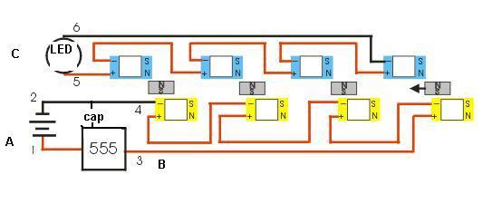
The induction coils are about 50 turns of 20 AWG magnet wire. Eight are used for the motor and eight for the generator, sandwiching eight 1/2 diameter by 1/4 thick neo magnets. Power to the motor section is supplied with four AA batteries through a 555 chip set up to pulse. Two potentiometers are used to control the pulse rate and duration. The coils are connected in series top and bottom.


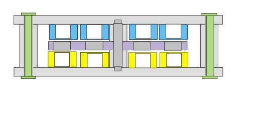
Here is a side view of the machine, which is machined plexiglas.


And here is the plan.


Initially, the unit requires a manual spin to get it going. An early test of the apparatus ran for 13 hours before the 2000 mAhr batteries discharged to the point they would no activate the chip. I have been unable to duplicate that time since, however have acheived 11 hours and now that I've used ball bearings on the shaft, I get 9 hours regularly (go figure). I am assuming 8000 mAhrs used per test and comparing the output at 5,6 in mAs times the hours of operations to see how they compare.


I don't know exactly what is happening, but here are the readings I get with the multimeter.


Power on.

At 1,2 the volts are 5.2 and ohms here are 13,700; Amps .0038

At 3,4 the volts are .62 DC .378 mV AC and ohms here are 1.4 Hmmm. I don't know what is going on here at this time.

At 5,6 the volts are 0 and the ohms here are 1.4


Spin the disc up. I don't have a tach, but counting the ticks per second, leads me to think I'm getting something like 500 to 600 RPMs. That is a lot more than I thought, based on the 555 chip specs which indicate 3 Hz at .33 Duty. Anyway, the spinning disc reaches an equilibrium and doesn't vary much, despite manipulation of the 20k pots.


Power on, disc spinning at ~500 RPM


At 1.2 the volts are 5.2; Amps .0038

At 3.4 the volts are 1.3; Amps .99

At 5,6 the volts are 1.09; Amps .78


This goes on for 9 hours but voltage tails off at 1,2. Finally I think it used 8000 mAhrs and generated 7007 mAhrs. 88% effecient it looks like to me.


But I'm pretty new at this and circuit analysis is pretty baffling sometimes.


I am posting here, as a rank amateur, hoping for some feed back from the many experts that frequent this board. If I were able to duplicate that 13 hour run, it seems like this contraption is extracting more power than it used? Is that promising enough to go on to Permogater II?

« Last Edit: July 10, 2004, 01:04:16 PM by (unknown) »

finnsawyer

  • Hero Member
  • *****
  • Posts: 1565
Re: The Permogator Saga
« Reply #1 on: July 11, 2004, 10:58:00 AM »
I suggest you beg, borrow, or buy an oscilloscope.  There are too many potential spurious effects that can be happening to rely on the multimeter readings.  The scope should allow you to "see" what is happening, as long as the device spins at a constant rate.  So far it doesn't look like anything strange is happening.  Keep in mind that you are going to get inductance effects from the coils.  Resistance values do not tell the whole story in this case.  I happen to be of the "no free lunch crowd".  That said, I would direct you to the various postings concerning "Over Unity" or the so called Bedini Motor.  You might check my posting concerning the same.  Have fun and enjoy the board.  
« Last Edit: July 11, 2004, 10:58:00 AM by finnsawyer »

Chester

  • Jr. Member
  • **
  • Posts: 55
Re: The Permogator Saga
« Reply #2 on: July 11, 2004, 03:02:14 PM »
The output from the chip is something like this:


The lower trace is from a capacitor connected across the chip.


From what I have been able to ascertain about inductor circuits here:


http://www.allaboutcircuits.com/vol_1/chpt_15/1.html


I think that the motor section functions as a pulsed DC induction motor. That is, the chip pulse induces a magnetic field in the coils which draws the magnets to them. Then, when the pulse is off, the inductors pulse the circuit also drawing the magnets to them. That is the only explanation I have for the RPMs being higher than the pulse rate. That is, the motor device is pulsing once for each pulse delivered by the chip effectively doubling the RPMs I was expecting. That may mean it is spining nearer 360 RPM. I have ordered a tach to check this out. A choice between an oscilloscope and new drill press has the drill press winning hands down for now. Maybe when Permogator II is built I will have some use for the scope, since it will be an alternator version.


One thing I forgot to mention about the multimeter readings is, that while the current is obviously pulsed DC, the meter only reads the pulsed current as AC. There is statement in the meter manual that AC current reading on a DC bias should be divided by .707, but I don't know if that is the case here.


If this explanation is correct, then the inductor coils are pulsing current back through the circuit half the time. I wonder what this is doing to the chip and batteries?


As far as the output of the generator, that seems to be straightforward. It is pulsing DC current at the magnitude indicated on the meter, perhaps at twice again the frequency of the motor through the action of the magnets. Make sense?


And I don't disagree there is no free lunch, but this device is simply dependent on the attraction of the magnets to the coils, and is independent of the power input, since the chip controls the frequency of the attraction rate. This is in accordance with the chip specs. This unit will spin fiercely on one AA battery using a reed switch until it burns up, since it just tries to spin faster and faster.


It seems, if there were more coils on the stator, properly positioned against magnets on the rotor disc, and away from the motor coils and magnets, one might expect quite a bit more output with the same input scheme.

« Last Edit: July 11, 2004, 03:02:14 PM by Chester »

finnsawyer

  • Hero Member
  • *****
  • Posts: 1565
Re: The Permogator Saga
« Reply #3 on: July 12, 2004, 08:59:54 AM »
The lower trace shows the capacitor alternately being charged and discharged by the pulse train.  When a capacitor charges or discharges through a resistor the resulting time dependence is exponential.  That's what it shows.  As far as the voltmeter readings are concerned the .707 factor only applies to ac waveforms that are sine waves.  You don't have that.  That's why I suggested the oscilloscope.  I'd also like to point out that in switching circuits you can get voltage spikes that can be hard to spot even with a scope.  A scope will help you sort out all the different phenomena.  
« Last Edit: July 12, 2004, 08:59:54 AM by finnsawyer »

Chester

  • Jr. Member
  • **
  • Posts: 55
Re: The Permogator Saga
« Reply #4 on: July 12, 2004, 08:10:21 PM »
I looked on Ebay and there are a lot of scopes for sale. But I'm confused by the amount of the offering there.


What kind of scope and what specs do you recommend, George?


Thanks.


Chester

« Last Edit: July 12, 2004, 08:10:21 PM by Chester »

finnsawyer

  • Hero Member
  • *****
  • Posts: 1565
Re: The Permogator Saga
« Reply #5 on: July 12, 2004, 09:00:24 PM »
I'd recommend a dual trace scope.  For the kind of work most people that use this board do a 1 to 10 Mhz sweep range is adequate.  It should support the X-Y mode.  You don't need to spend a lot.  Check my comments and postings on this board for some ideas for using a scope.  Good luck.
« Last Edit: July 12, 2004, 09:00:24 PM by finnsawyer »

finnsawyer

  • Hero Member
  • *****
  • Posts: 1565
Re: The Permogator Saga
« Reply #6 on: July 13, 2004, 10:45:57 AM »
I took a look on E-bay.  The Kikusui looks like a nice unit.  It's more power than you need being a triple trace at 60 mz.  My scope has the same specs and cost me a lot more.  Course getting it at or near $70?  You might check into buying a new one, say a dual trace with one mhz sweep.  They're not too expensive.  Edlie electronics carries a line by Elenco, but they don't list them on their web site.  As far as the Textronic scopes They were good for their day (and expensive), but they may now be 30 years old.    
« Last Edit: July 13, 2004, 10:45:57 AM by finnsawyer »

Chester

  • Jr. Member
  • **
  • Posts: 55
Re: The Permogator Saga
« Reply #7 on: July 13, 2004, 04:14:15 PM »
That looks like a pretty good price, if it stays. No bids yet. Guess I'll be up at 2:30 a.m. and try to buy it. If not, there are a couple more units offered by the same seller in a day or two; a HP 1420A, for instance at 50 bucks. I doubt either of these comes with a manual or probes, though. The Elenco models appear to be over 800 dollars per their on line catalog. Jeebus.


Received the magnets today for Permogater II. I got them from National Imports (cheaper) and they did a nice job of packing them. These are the alternator magnets 3/4 by 1/8 times 60. I already have the motor magnets. Now, I'm just waiting on the bearings and the drill press to start whittling away. Decided to go for a little more precision than the eyeball method of drilling crooked, off center holes, this time. Besides, there are so many more to do and they are bigger holes.


If anyone is interested in a fairly cheap photo tachometer, All Electronics carries one for about 50 bucks, the same type that Grizzly carries at 75 or elsewhere can be hundreds.

« Last Edit: July 13, 2004, 04:14:15 PM by Chester »

Chester

  • Jr. Member
  • **
  • Posts: 55
Re: The Permogator Saga
« Reply #8 on: July 14, 2004, 08:48:10 AM »
I was the only bidder. 70 + 40 freight. Should get the unit in a week or so.


Chester

« Last Edit: July 14, 2004, 08:48:10 AM by Chester »

artv

  • Sr. Member
  • ****
  • Posts: 459
Re: The Permogator Saga
« Reply #9 on: June 16, 2010, 08:44:47 PM »
I just wish I could see the pics .......sometimes they load sometimes they don't......artv