I am posting this to update Ron and other interested parties on my wind turbine blade project. The CNC mill is slowly progressing, Although I have a few bugs to work out with alignment, so for now I only have the small mill to work with. As I am working my regular job and a couple of part time jobs right now, along with getting a bunch of apartments ready for re-leasing on 1 August, time has been, and for the short term will be an incredibly scarce comodity for me. To take full advantage of the mill, I have been trying to program in visual basic, an application to generate the G-codes necessary to run the machine to generate a blade profile. I started with a NACA 4415 profile for this project, as was suggested by Ron, (wdyasq), from here. I found data for this profile in the University of Illinois at Urbana Champaigns on-line airfoil database. This is a great resource to have available to us, and is located here:
http://www.aae.uiuc.edu/m-selig/ads.html
My thanks go out to the University of Illinois for making this data available to us. I attended the Chicago Campus quite a few years ago for my undergraduate studies.
Next, one has to figure out what angles and dimensions the airfoil is to have at each incremental section of the blade. To do this one has to have an equation that relates the ideal angle and chord width of the airfoil to the position out from the center of the blade radius. This was pointed out to me by Ungrounded Lightning Rod when I made the small two foot diameter blades here:
http://www.fieldlines.com/story/2005/2/22/111119/599
To formulate the best approximate equations for the ideal angles and chord widths, I did a search on the web, and of course ran across a wealth of information posted by Hugh Piggot (scoraig wind), the father of the modern dual rotor axial designs built by so many of us here. He has posted a wealth of information on the relationships of the chord and angles to the size of the rotor, the number of blades, and the position out from the center. It took me quite a while to grasp most of the concepts he goes into, and I still have quite a bit of work to do there, but, having had a few fluid dynamics classes in the past, at least I was familiar with Reynolds numbers, and viscosity and such. I have to get a copy of his book, I think I'll order one from DanB at Wondermagnet.com as soon as I finish this posting, as he has obviously put a lot of talent and thought into the concepts involved here. I did find other information posted on line, but his was the most thorough I ran across. There is an HTML version of some of his notes posted here:
http://users.aber.ac.uk/iri/WIND/TECH/WPcourse/page1.html
or the PDF version which Hugh has made available on his site here:
http://www.scoraigwind.com/wpNotes/index.htm
I used these approximations for the calculation of the ideal chord width and blade angle as I have yet to find a serious flaw with them or a better approximation.
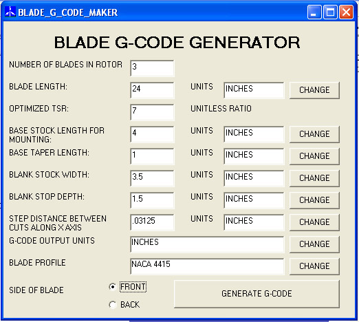
I built a basic interface to enter the parameters:

Interface to input blade parameters
To calculate the y and z coordinates for each position out along the x axis from the center the following steps are being programed:
First I calculate the ideal chord width and the blade angle.
Next I convert the blade coordinates to polar coordinates
Then add the calculated ideal blade angle, and then convert back to rectangular coordinates.
Then I calculate the minimum x and y values, because of the profile shape for the NACA 4415, these are always less than or equal to zero.
The profile is then shifted along the x axis so that the minimal value is zero.
This is repeated along the y axis, so that not the entire profile has x and y values that are all greater than or equal to zero.
Next a check is made to see if the maximum x and y values would fall outside of the material, and if this is the case, for right now, the size is scaled such that the maximum x and y values fall on the edge of the material. (I still plan to, and have to change this so that the angle is adjusted in the case where the material is wider along the y axis to take full advantage of that width)
Once this is scaled you have the basic profile for that position along the x axis, or station. (this is as far as I have programmed, and as mentioned above, I still have a few modifications to work in)
Now, you have to do a little math on the profile to generate the x, y, and z positions for the g-codes. If you are machining the front, then you have to machine to a depth of the negative of the z-value, and flip the profile around on the y axis from the basic profile provided by taking the width of the stock and subtracting the y value. For the back side, the y-axis is OK, but you have to take the stock thickness and subtract off the value of the z coordinate from the profile to come up with the depth to machine to. Then on top of this, this takes into account no tool offset, which would be fine for round nose bits, but I intend to use regular flat bottomed end mills, so I will have to compensate for that, which may involve some more complicated calculations, depending upon whether the next station is deeper, or more shallow than the last, and the diameter of the end mill. I have some more thinking to do on that.
For the base of the blade, I intend to taper the stock shape of the material into the first profile, and have included a variable to be entered which will indicate how steeply to do that. basically, for each of those x-positions, it will generate the first profile, and then calculate the percentage of the depth equal to the percentage of the distance from the start of the taper to the first station. I'm not sure how this will look, but we will see.
I also have to provide for the generation of the g-code syntax as this will generate the lines of text and add them to a text file for each x-position from the root of the blade serially out to the tip.
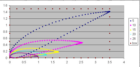
For now, I can generate the profiles only. Here is an example of five stations exported to excell and ploted. The series name represents the distance in inches from the center for a tsr=7 26" blade carved from a standard U.S. 2 by 4, the outline of which I added to the plot as a box.

small sample blade stations for 26 inch tsr 7 blade 3 blade rotor from a 2 by 4