On to the next project. Problem posed, can a wind mill power supply be made from old parts and junked equipment. Here is a lot of old equipment.
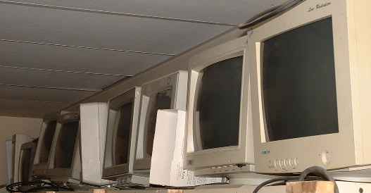
And still some more of these computer power supplies.
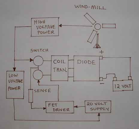
"Concept Drawing of How to Control High Voltage Power"
The idea seems simple and comes after the wind-mill is producing power.
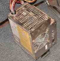
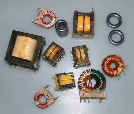
The next step is to start collecting parts that will do the job. There are lots of these things in the supplies and monitors. All different sizes and types and who knows the wires in them? These are the good ones shown below.
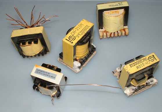
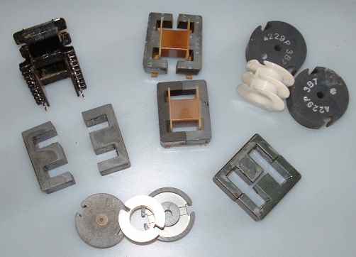
Can you tell the difference? The first ones are high frequency type material and the second ones are low frequency material.The second ones will not work for high frequency transformers.
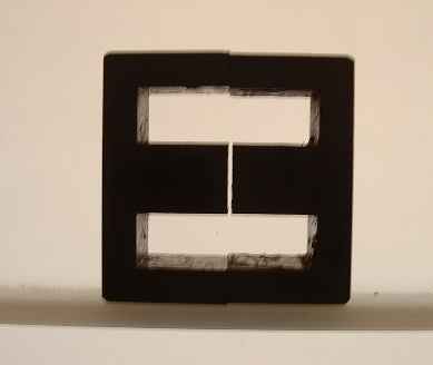
Now to make some useful parts out of the old transformers. First I had to break the core in half. This can be a lot tricky. I lucked out this time and picked one that cracked like an egg. I collect these things and then add them to my collection.
Now time for a circuit drawing.
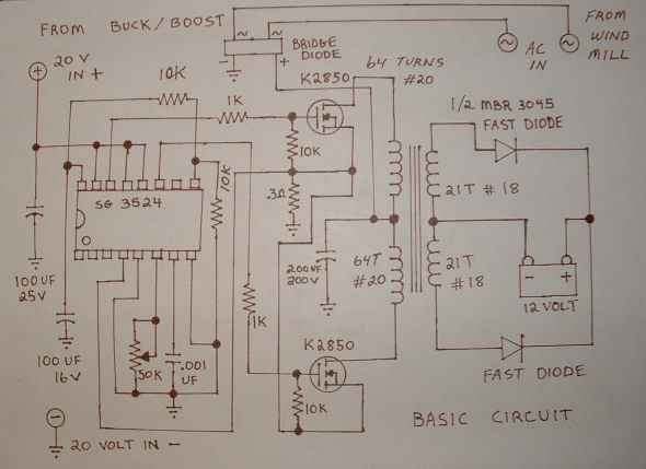
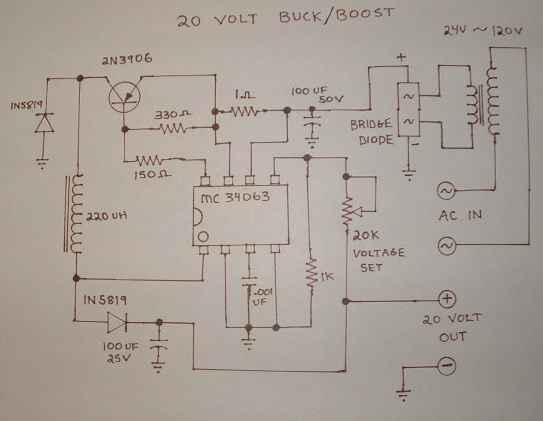
This is the basic inverter circuit and should give me a simple understanding of the parts required. There is a FET driver power supply in the next circuit diagram.
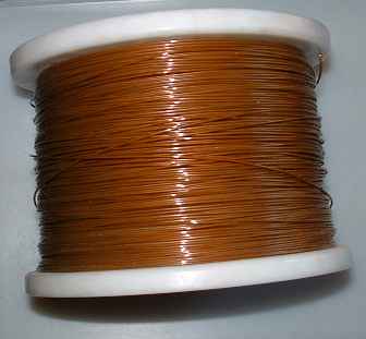
Winding the transformer is one of those things that I have done many times before. This time it will be wound differently. Guess work I guess. Wire size, let me see what size of wire is in stock. Have some 18 gauge and 20 gauge. The larger number is smaller wire and the smaller number is larger wire. Looks like I will use the thinner wire for the primary windings and the thicker for the secondary. Wire comes in a large roll if you want to get it cheaper.
Start winding or I will be here all day.
62 wraps of # 20 gauge 31 wraps per row. This is done twice to give me two complete coils of 62 turns # 20 gauge. Yellow mylar tape is added to insulate between the primary and secondary coils. There are 30 Turns #18 gauge in the secondary and two of these coils are added to finish the secondary.
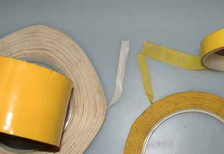
This white tape is also use to hold and insulate the coils.
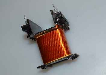
The core on this one has a small air gap and you can see it in this picture
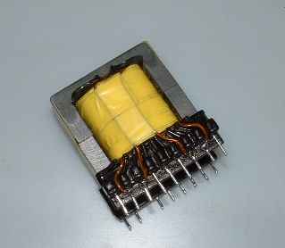
A finished core, hand wound and ready to add the the circuit.
Hand wired inverters, I was told, will not work. Funny thing this one works fine.
Finished Proto Type
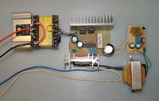
Just a bit of testing now.
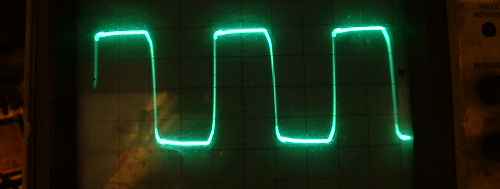
And some more testing.

The project works but has a few draw backs. This type of work is akin to witchcraft. I am looking forward to making the next one. 45~120 VAC in 15~40 VDC out. Any questions? Bill
