Short version,
Layout with Autotrax; print on laser printer to transfer film; laminate onto copper pcb; etch; trim; drill; populate.
Long version with pics.
Autotrax is a Dos program which runs just fine on Windows if you set it to full screen mode.
It is available from
http://www.altium.com/Products/AltiumDesigner/Licensingoptions/AltiumDesignerProtellicense2004/Downl
oads/AltiumFreewareEndUserLicenseAgreement/Autotrax/
Updated video (and printer) drivers are available from
http://www.airborn.com.au/layout/easytrax.html
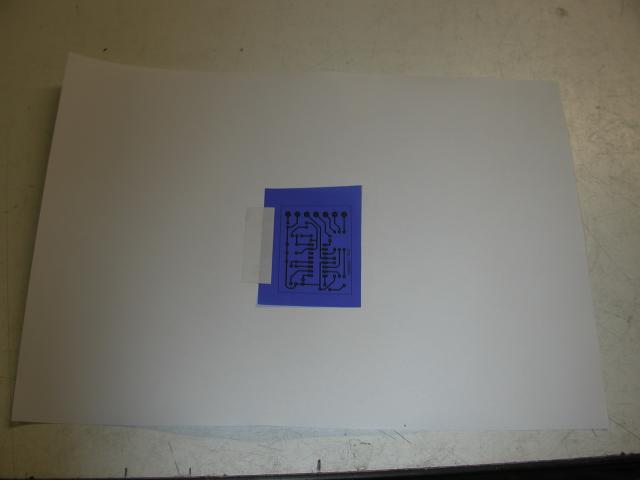
The transfer film I use is called press n peel blue. First I print the copper side image to paper, stick a piece of the blue film over the printout, then feed it through the printer a second time and print onto the blue transfer film.
Make sure you stick it down on the leading edge as it feeds through the printer.
Turn off toner saver and set it to print as dark as possible to impart the maximum amount of toner possible.
This is what it looks like after the second pass through the printer.
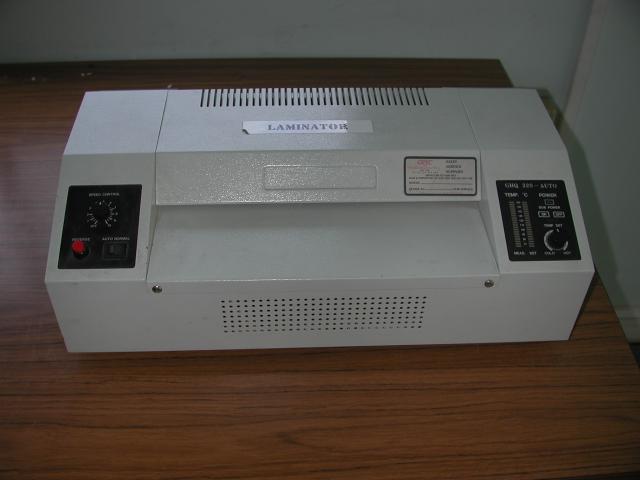
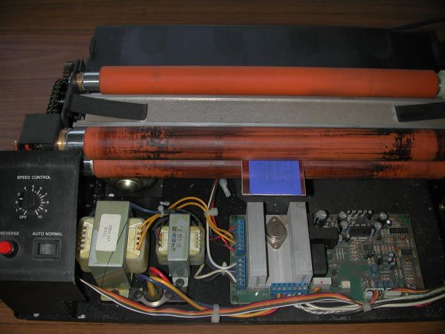
This is the hot laminator I use. Some notes later on a cheaper alternative.
The instructions with the transfer film say to use a hot iron. Take it from me; forget it. You can't get enough heat and pressure using a hot iron.
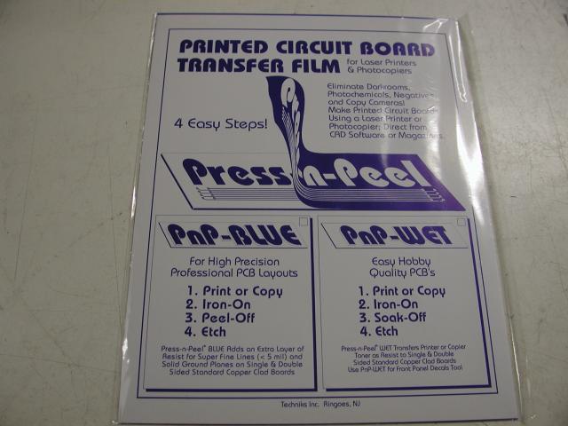
This is the film I use. I source it from Jaycar in Australia, but it should be available world-wide.
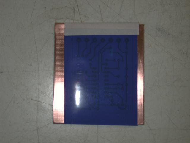
Here's the film set up on a blank piece of copper ready for the laminator. I clean the copper with stainless steel wool, 1200 wet n dry, then finish with isopropanol alcohol. Cleanliness is key at this point. No greasy finger marks.
Feeding the prepared board into the laminator. I remove the cover of the laminator to get easier access to those heated rollers. I set it to 140 deg C and the speed to number 2. Nice and slow and pretty warm. Temperature will vary slightly depending on the toner in your laser printer. Small boards I run through twice. Larger boards I run through 3 times.
After the laminator, drop it straight into cold water and let sit for a few minutes.
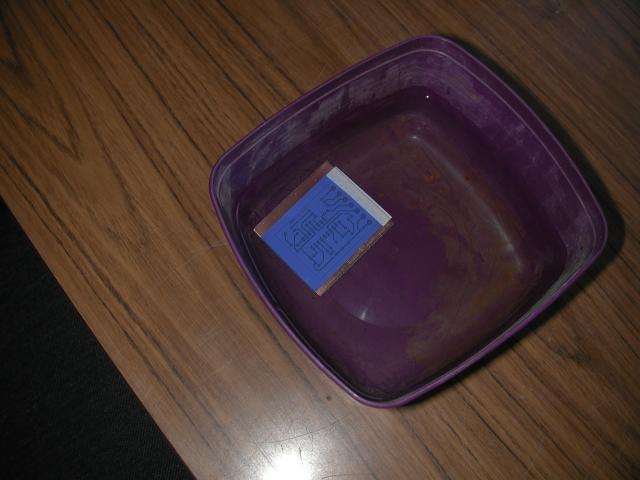
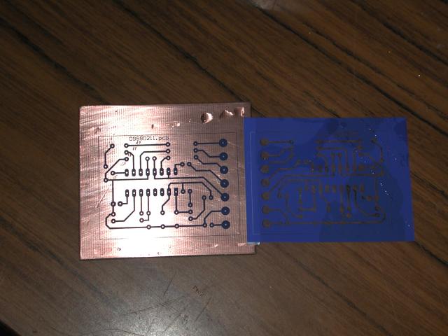
Now the film should just peel away easily, leaving the toner on the pcb.
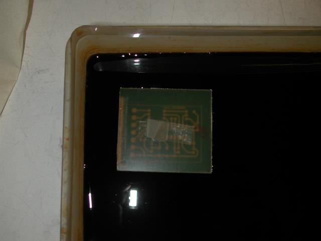
Into the ferric chloride. I float it on top, and make a loop of sticky tape to insert/remove the board.
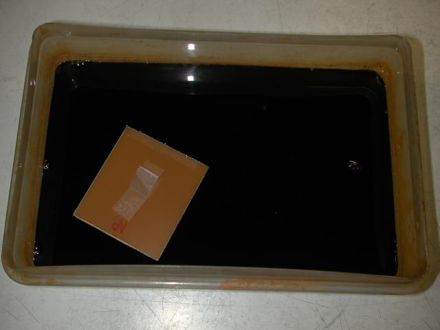
After a few minutes, or longer as the etchant gets used up, it is now etched and ready to be removed and rinsed under cold running water
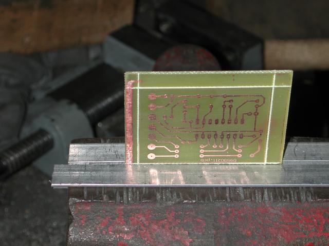
I then score the outline of the pcb with a Stanley knife on both sides (boxcutter in some parts of the world I believe) and snap it in a bench vice.
The sticky paper I use to hold the transfer film in position is manufactured by Avery, and sold as laser printer labels. I use the full A4 size sheets and cut off strips as needed. This stuff will handle the heat of the laser printer and the laminator. Don't try and use sticky tape. This stuff is also great for making meter faces as in my combined metering board.
As for the laminator. I am lucky in that my employer has this laminator that I can use. The rollers are spring loaded, so the thickness of the pcb is not a problem. I did for a while use the heated rollers out of an old HP laser printer until I lost control of the heating elements and cooked it.
You can buy a cheap laminator and modify the rollers to do this. More information on this site;
http://www.pulsar.gs/PCB/a_Pages/4_Products/4d_Toner_Applicator/Toner_Applicator.html
Down near the bottom of the page is a link to a pdf detailing modifications for normal 64 thou pcb.
And there you have it. Less than an hour from an image on the computer to a pcb ready to drill. That time included taking photos and being side-tracked by the boss wanting to work on what he considers real work. That one hour was a lot less than it took me to write this howto.
And if you really want to know, that particular pcb is a switchmode controller pcb for the upcoming Grand Unified Dc-Dc Converter.
Amanda
