Author Topic: 5.25" dual rotor VSs test continues.  (Read 4887 times)

0 Members and 1 Guest are viewing this topic.

Jerry

  • Hero Member
  • *****
  • Posts: 1519
5.25" dual rotor VSs test continues.
« on: February 28, 2007, 03:31:35 AM »
I was able to set up the additional test. The first test were done at just a couple amps so no thermal testing could be done.


It was evedent from the first test higher rpm and a lower battery voltage load would be requiered for higher amperage and higher heat testing.


The first test with the smaller GE motor and the large yellow 12 volt battery was conducted at my retail store/shop.


Todays test was done in my home shop. It was cold but i got it done.


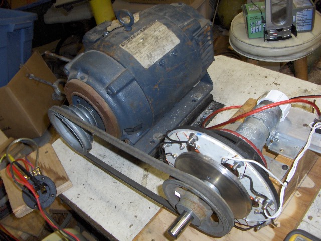
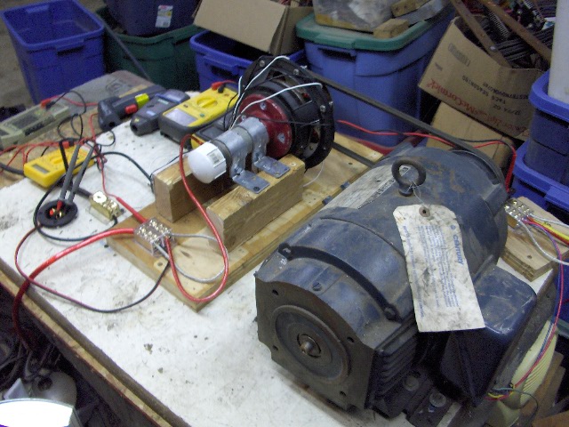
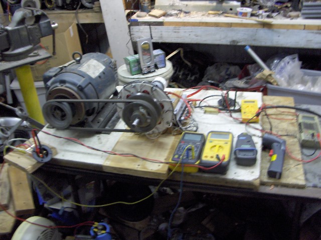
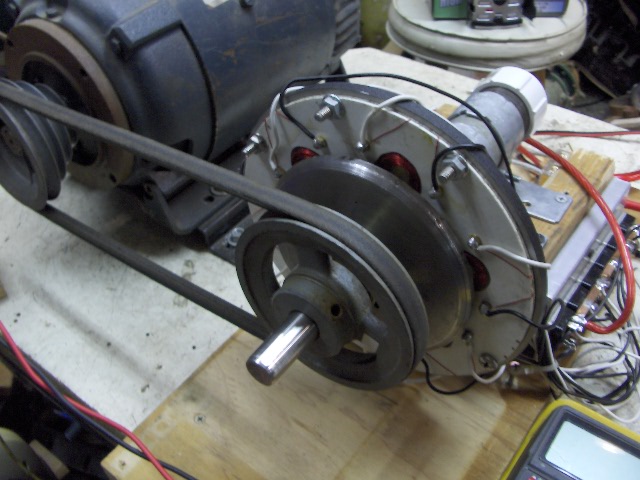
I used 12 each 6 volt golf cart batteries wired in perelell. I figured this should provide a fairly solid load. I set the PMA up with a belt drive from a 2 HP 180 volt DC motor.


I have a 5KW variac here also and a 200 volt power supply. So 0 to 200 volts dc to vary the rpm.


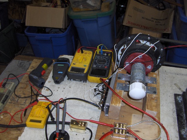
I used 4 digital meters. I measured voltage and amperage going into the drive motor and voltage and amperage going into the 6 volt battery bank from the pma.


I also used an infered remote thermomiter and an infered romote digital tachometer.


Since the alt has been tested at very low amperage I omited these #s here and will report #s at 12 amps, 15 amps and 20 amps.


I tested the star stator first. Here are the #s.


 12 amps at 1509 rpm, temp 49%, drive motor at 360 watts.


 15 amps at 1722 rpm, temp 90%, drive motor at 500 watts.


 20 amps at 2165 rpm, temp 100%, drive motor at 832 watts during this test the armature started to get real hot and I could start to small hot reson.


 Next "Jerry Rigged" #s.


 12 amps at 1432 rpm, temp 42%, drive motor at 322 watts.


 15 amps at 1563 rpm, temp 47%, drive motor at 408 watts.


 20 amps at 1802 rpm, temp 53%, drive motor at 598 watts.


I drove this stator up to 25 amps then it began to get hot after a while. Star got real hot real fast at 20 amps.


Here are several things I have determined from these test.


 1. star requiers higher rpm.


 2. star produces less power at the same rpm.


 3. star requires more drive power.


 4. star produces more heat in the coils while at the same time requireing more drive power and produceing less.


I've noticed very simular results in last years GM alt test and the 3 phase motor conversion.


It has been sugjested that wave form would effect these test results. I don't think a GM alt, a 3 phase motor conversion and a dual rotor disc alt would have the same wave form and yet they had very simular test results.


I do have more testing to do on a few more disc alts. I think the fun will be with the larger high amperage machines.


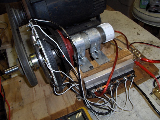
Here are a few pictures of todays test set up.


I have a few more dual rotor alts started but it will be some time befor there ready for testing.


                           JK TAS Jerry

« Last Edit: February 28, 2007, 03:31:35 AM by (unknown) »

Flux

  • Super Hero Member Plus
  • *******
  • Posts: 6275
Re: 5.25" dual rotor VSs test continues.
« Reply #1 on: February 28, 2007, 01:30:39 AM »
Well done Jerry.


This machine was the one that I predicted would show the most benefit from your connection. It will be interesting to see what happens on the other machines..


It is a pity that you can't compare your connection with delta under these conditions.


To do so you would have to parallel the opposite coils and that would almost certainly introduce circulating currents.


I can't comment on the car alternator, I have never played with them, but I do think waveform is the main issue with these axial machines.


I am beginning to see what is going on here and if you could get those waveforms it would be useful.


Your findings make sense, the temperature rise is related to the internal losses so it is no surprise that you see a much higher temperature rise in the star case.


My own tests seemed to show that with a design that suited star there was not a lot of difference between your scheme and star. Delta was worse than either in terms of part load efficiency but gave greater output than star for a given speed.


It is too early to make much comment except to say that with small machines loaded in the way you load them your method does seem to have significant advantage.


For those who build larger machines with a very low cut in and work in stall to get good low wind performance and easy control at the expense of top end efficiency your method may not show any significant advantage.


With the methods of loading that I have been playing with, I suspect that star will prove to be the best way but if there is a winding geometry that reduces the part load harmonic loss then your method may still have some advantage.


Keep up the good work, I just don't have time to do all these tests, but when I have a better understanding from your results I may find time to follow up your work.


Flux

« Last Edit: February 28, 2007, 01:30:39 AM by Flux »

Devo

  • Full Member
  • ***
  • Posts: 175
Re: 5.25" dual rotor VSs test continues.
« Reply #2 on: February 28, 2007, 05:08:48 AM »
Jerry I am mid way building 3 genny's right now,If I understand this right you have six coils , each coil has it's own bridge rectifier & then after that the bridges are all in parallel or series?


 I tried this set up on my 8 foot originally but went with star as the results seemed much closer in my testing & star actually beat out the individual rectified one with voltage per rpm & amps but I had no way to check heat or drive power 2 major factors.  


I may do one each way & put them both on test towers outside the shed to see real life comparison , they would be 12 mag per rotor, dual rotor 12/9 arrangement.


If you are interested say the word & I will do 1 each way.I would like to do 1 in star with a star delta switch & an over sized prop to drive it at low rpm's in star But I'm having trouble finding a supplier for a star delta switch.


Great testing as always...


Devin

« Last Edit: February 28, 2007, 05:08:48 AM by Devo »

Jerry

  • Hero Member
  • *****
  • Posts: 1519
Re: 5.25" dual rotor VSs test continues.
« Reply #3 on: February 28, 2007, 08:56:49 AM »
Hi Devin.


Did you build 2 seperate stators. You can't simply build 1 stator, wire it star and then take that same stator and wire it "Jerry Phase" or as I've just been addvised open delta.


In my test alt there are 6 coils. In star power is taken from 4 coils at any given instant because at any given instant only 4 coils are at or within 85% of makeing power the other 2 are just not makeing power.


What this means is if 1 indevidual coil is makeing 5 volts then 4 of these coils wired in sires only produce a total of 17 volts.


What I've done here is to wind coils with wire 1/4th the size but wind 4 times the turns so that each individual coil produces that 20 volts. Now use a fullwave bridge on each coil.


Then perelell all 6 rectifiers DC output. The amperage is the sum of all 6 coils.


This means that the power from each coil has 100% of its power delivered to the load.


In star only 85% of the power from each coil is delivered to the load. In star power delivery to the load is degraded by passing its power through a neihboring phase that is in partial oposistion to that delivery.


In "Jerry Phase"  as far as heat is concerned each coil is working at 33% duty cycle.


In star each coil is working at a 66% duty cycle.  


To make this compairison 2 seperate stators are required. 1 stator is not correct.


A "Jerry Phased" stator can be wound of wire just 1/2 the wire circular mills and the coils of each phase wire in sires and each phase conected to its own and seperate bridge with the same results.


Part of the reason I did this was because I had the wire and part was to ilistrate the dramatic diferance. I knew eye brows would lift when I stated I was building a stator with 24 gage wire.


For those that still are not understanding my point of view here I ask this question.


How does the power from each coil in star get to the load, what path does it take?

 How dose the power in each coil in "Jerry Rigged" get to is load, what path does it take.


In star the power from each coil or phase must pass through its out of phase neighbor and  neither 1 of these phases are at there peak output at the same time so neither one can deliver its full power at any time.


As a mater of fack a star phase spends about 15% of its power just powering up it neighbor or causeing heat rather then delivering that power to the load.


In "jerry Rigged" there is no such power waist or obstruction. Power goes straight to the load with no nasty neighbor to opose power devivery no dead coil to heat up or cause resistance on the way. If it wasn't so I wouldn't be getting the results I'm seeing.


I invite any one to do the same test I've done. But do these tests with as much accuracy as posable keep both stators as simular as posable. Poure from the same mold so to speak.


3 phase power from the power company is a standard. When it gets to the end user it is most often powering a 3 phase motor. This 3 phase motor is set up to accept this 3 phase power correctly it has 3 phases set at 120% diferance and the power is accepted and used in corect phaseing but when we combine all 3 phases into 1 common dc source through rectifiers star has cotradicting factors.


Thats why equptment such as my large 3 phase welder and 3 phase battery charger do "Jerry Rigged" or open delta. Otherwize heat and pour eficientcy would result.


The testing and discusion goes on.


                          JK TAS Jerry


« Last Edit: February 28, 2007, 08:56:49 AM by Jerry »

Flux

  • Super Hero Member Plus
  • *******
  • Posts: 6275
Re: 5.25" dual rotor VSs test continues.
« Reply #4 on: February 28, 2007, 09:16:38 AM »
Open delta has a specific meaning and is not the same as this. I would prefer not to use that term to describe this connection.


It is quite right that you can't directly compare a single stator in star and Jerry connected or delta, at the same voltage.


for anyone wanting to try the equivalent of star/delta connection, it is much easier to use star/Jerry as it can be done with only one switch or relay contact. The result will also likely be better than star/delta. It does still leave the issue of the star connection causing stall in the lower winds if the winding is wound for the high wind case, but would give some advantage over a single connection.


Flux

« Last Edit: February 28, 2007, 09:16:38 AM by Flux »

ghurd

  • Super Hero Member Plus
  • *******
  • Posts: 8059
Re: 5.25" dual rotor VSs test continues.
« Reply #5 on: February 28, 2007, 09:34:39 AM »
What Flux said is why it works for me.


I am in the habit of throwing a pile of magnets in a small motor to see what happens.

It tends to make a lot of voltage, too much, because small motors have a lot of turns. And lots of resistance.


Rewinding is something I can not accomplish in a small motor, meaning I have whatever stator it started with.

Jerry Phase raises the cutin and lowers the resistance, with a bit better output than Delta.


Jerry, is that why you came up with it?

G-

« Last Edit: February 28, 2007, 09:34:39 AM by ghurd »
www.ghurd.info<<<-----Information on my Controller

TomW

  • Super Hero Member Plus
  • *******
  • Posts: 5130
  • Country: us
Re: 5.25" dual rotor VSs test continues.
« Reply #6 on: February 28, 2007, 10:08:41 AM »
flux;


Would you kindly give a link or explanation of what "open delta" means in your context? I have heard of it before but know no details.


I use the rectify each phase separetley on a conversion due to phase mismatch in the windings that kills output otherwise. I "think" this is what is becoming known as "jerry phased" but I really have not watched this discussion topic very closely.


I just think of it as independently rectified.  


Thanks for any input.


Cheers.


TomW

« Last Edit: February 28, 2007, 10:08:41 AM by TomW »

wayne

  • Jr. Member
  • **
  • Posts: 94
Re: 5.25" dual rotor VSs test continues.
« Reply #7 on: February 28, 2007, 10:35:55 AM »
Flux


Maybe I missed the boat somewhere but what is open delta and is there a picture of this. Or is it just each phase with each of its own bridge, and all in parallel. And a drawing of a switch/relay to change from star to open delta/Jerry rigged.


Thks

Wayne

« Last Edit: February 28, 2007, 10:35:55 AM by wayne »

Flux

  • Super Hero Member Plus
  • *******
  • Posts: 6275
Re: 5.25" dual rotor VSs test continues.
« Reply #8 on: February 28, 2007, 11:18:42 AM »
I will try to explain without a drawing.


Assume you have a 3 phase supply and you want to transform its voltage to 3 phase at a different level, you can obviously use a three phase transformer, but you can also do it with 3 single phase transformers, these can be connected star/star, delta/delta or combinations of star/delta to achieve the voltage you want.


If you think in terms of the delta/delta case, the phase angle and voltage information is conveyed if you only use two of the 3 transformers, you will reduce the rating and on load there will be some departure from the true 120 deg displacement but it will work. It is just a delta connection with one of the legs inferred. It is often used where power is low and low cost is a priority, the most common example is the voltage sensing transformers feeding an AVR ( automatic voltage regulator).


Open delta refers to the ac connection, it has nothing to do with rectifiers.


I have never come across a name for what Jerry is doing with each phase rectified separately, at least here it seems simpler to call it jerry connection ( not sure I like Jerry phase).


At first sight it seems as though jerry's method is identical to delta, it is at least as far as the peak voltage is concerned, but the delta connection without reactance is forced to operate as a conventional 3 phase bridge rectifier where the line currents alternately carry current just as for the star case. There is no overlap in diode current.


Jerry's method is just 3 single phase supplies displaced 120 electrical degrees, rectified and summed as 3 single phase units. Conduction for each phase takes place when the emf is above the battery voltage and there is no restriction on the number of diode paths conducting at any instant.


Flux

« Last Edit: February 28, 2007, 11:18:42 AM by Flux »

coldspot

  • Hero Member
  • *****
  • Posts: 843
  • Country: us
Re: 5.25" dual rotor VSs test continues.
« Reply #9 on: February 28, 2007, 02:17:57 PM »
Well done Jerry !!!!!!!!!

:)

This is working out the same with the testing as it seemed to work in my head when thinking it thru.

I still can't see what the issue is that other people can't just think it thru and see the difference and belive what the results should be from this line of thought.

????????????????????????

I being with only a small amount of electrical smarts, ( A degree in "Electrical Tech" from a university, {ok, ok was 20+ years ago}), but can and do see this line of thought as just plan simple commence sense.

 Anyway,

Thanks you again and please keep playing and posting the info for all to see and read!
« Last Edit: February 28, 2007, 02:17:57 PM by coldspot »
$0.02

Devo

  • Full Member
  • ***
  • Posts: 175
Re: 5.25" dual rotor VSs test continues.
« Reply #10 on: February 28, 2007, 02:33:25 PM »
Thanks Jerry I see why my test didn't turn out right. After some hunting on magnets & figuring out the surface area of different magnets 1/2" thick I have stuck with the 2" x 1" x .5" 42 Grade neo's as I can get the extra 50 % magnet area of the 2" rounds by adding more magnets if I choose for less cost..


I have a few 10 pound rolls of 17 Guage wire coming &  magnets.If I wire one stator with 2 0r 4 in hand #17  as star  & the other as half that either 1 or 2 in hand with each phase of 3 coils rectified seperate I will have 2 similar or comparable stators correct?


If so I will run 6 wires down the test towers for 2 mills  to compare.


Thanks for all the work you have put into this as if the heat is less it will be a much cheaper way to increase power instead of more magnet mass & thicker wire.


Would a 4 to 1 mill size with each coil rectified seperate have any advantage over a 2 to 1 mill size with the "phase" restified?


Devin    

« Last Edit: February 28, 2007, 02:33:25 PM by Devo »

Devo

  • Full Member
  • ***
  • Posts: 175
Re: 5.25" dual rotor VSs test continues.
« Reply #11 on: February 28, 2007, 02:48:11 PM »
Flux


Star/Jerry would mean that instead of going to delta when the stator is getting hot the three phases are each parelleled(not sure on spelling) after an individual bridge correct?


The trouble I have with Star/Delta or Star/Jerry is the electronics. I have no Idea how to make something that can automatically sense when it is time to switch...


I can make a manual switch but this wouldn't be good for me as I am not home enough to control it to the wind.(Jerry sorry for taking your thread sideways I will start a diary when my stuff comes in & continue the Star/Delta questions when I start my build)..


Devin


« Last Edit: February 28, 2007, 02:48:11 PM by Devo »

Jerry

  • Hero Member
  • *****
  • Posts: 1519
Re: 5.25" dual rotor VSs test continues.
« Reply #12 on: February 28, 2007, 07:24:55 PM »
Last year my test on the motor conversion had simular results.


I had rewound that motor with 2 in hand. This gave me the ability to wire the coils either in sires for "Jerry Rigged" or perelell for star.


Neat thing about this is only one stator is requiered to test both wireing scheems.


I'm thinking about winding the coils for the 4ft Hugh Piggot alt this way.


This alt uses 8 of the 1"X2"X1/2" NEOs in a single rotor design with 6 coils wound of 85 turns each of 16 gage wire.


I will wind 85 turns with 2 in hand of 19 gage wire. In this design the "Jerry Rigged" coils will have twice the turns count as star and there will be 1 fullwave bridge per phase.


16 gage is 2583 circular mills at .004 ohms per ft. and 19 gage is 1288 circular mills at .008 ohms per ft. This will be the perfect match.


For star the 2 in hand per coil will be wire in perelell. In "Jerry Rigged" the 2 in hand per coil will be wireed in sires.


Neat, great I only need to build one stator for this test. I have the magnets, steel discs, fiberglass discs, wire and well every thing. Now all I need is time?


I also plan on testing this alt with a none magnet second disc and then add magnets to that disc latter. I'll be testing diferant 4ft blades on this alt with a small temperary wind tunnel.


Here we go again.


                          JK TAS Jerry

« Last Edit: February 28, 2007, 07:24:55 PM by Jerry »

tecker

  • SuperHero Member
  • ******
  • Posts: 2183
Re: 5.25" dual rotor VSs test continues.
« Reply #13 on: February 28, 2007, 09:13:51 PM »
 This method is much more conducive to charging low voltage than three phase to me. If your end product is low voltage dc for storage why not use a stator that has 12 to 48 volt taps instead of tring to use devices down line that don't match the load . a few switching circuits and your done low rpm series the bridges until the matching rpm is there and switch .
« Last Edit: February 28, 2007, 09:13:51 PM by tecker »

willib

  • SuperHero Member
  • ******
  • Posts: 2414
  • Country: us
Re: 5.25" dual rotor VSs test continues.
« Reply #14 on: February 28, 2007, 10:01:29 PM »
Jerry this seems to be a new configuration of your speaker cage wind turbine.

even though this one only has one rotor , it could have two , and still use only one speaker cage?

i know i asked this before , i apologize , but dont remember your reply.

what do you use to  connect the shaft to the rotors?

also what size bearings (ID) & (OD) are you using , i'm sure i could find the answer , but i would have to go through many , many of your posts to find the answer.. :)
« Last Edit: February 28, 2007, 10:01:29 PM by willib »
Carpe Ventum (Seize the Wind)

Flux

  • Super Hero Member Plus
  • *******
  • Posts: 6275
Re: 5.25" dual rotor VSs test continues.
« Reply #15 on: March 01, 2007, 12:41:48 AM »
Devin


The easiest way to derive the switching signal is from frequency.


Commanda has details of a frequency switch somewhere that would do the job.


Hugh Piggott has a heating controller on his site, the first stage of which is a frequency switch using the 2917 tacho chip.


If you Google 2917 it should get you to the National Semiconductor site where you can download the data sheet. I am fairly certain it shows a frequency switch in the applications. When I played with star/delta I used a circuit based on that.


It is possible to do the switching from current rather than frequency and I once did a small machine that way, but speed( frequency) is by far the best thing to sense.


Flux

« Last Edit: March 01, 2007, 12:41:48 AM by Flux »

stop4stuff

  • Sr. Member
  • ****
  • Posts: 263
Re: 5.25" dual rotor VSs test continues.
« Reply #16 on: March 01, 2007, 12:46:36 AM »
Devo, here's a 3 phase star/delta switch I made a while back;

http://www.fieldlines.com/story/2004/5/26/15451/3307
« Last Edit: March 01, 2007, 12:46:36 AM by stop4stuff »

Darren73

  • Jr. Member
  • **
  • Posts: 98
Re: 5.25" dual rotor VSs test continues.
« Reply #17 on: March 01, 2007, 01:11:29 AM »
Flux,

The term open delta does not just refer to the transformer case you give, it refers to any circuit where the wireing does not form a closed delta. the fact that Jerry has multiple parallel circuits for each of the 3 phases makes no difference to this, it is still fundamentaly open delta, if however he was to change to any other configuration than the 3 phase then it would no longer be open delta.


Regards

Darren

« Last Edit: March 01, 2007, 01:11:29 AM by Darren73 »

Flux

  • Super Hero Member Plus
  • *******
  • Posts: 6275
Re: 5.25" dual rotor VSs test continues.
« Reply #18 on: March 01, 2007, 01:26:34 AM »
Devin


Not sure where this will turn up, but this was the circuit I used.


The transformer can be very small and 120V to 6v or similar will do. The primary is fed from a pair of ac lines.


C1 sets the speed range, probably start with .22Uf. 10k pot gives fine speed setting.


« Last Edit: March 01, 2007, 01:26:34 AM by Flux »

ghurd

  • Super Hero Member Plus
  • *******
  • Posts: 8059
Re: 5.25" dual rotor VSs test continues.
« Reply #19 on: March 01, 2007, 10:41:44 AM »
« Last Edit: March 01, 2007, 10:41:44 AM by ghurd »
www.ghurd.info<<<-----Information on my Controller

Jerry

  • Hero Member
  • *****
  • Posts: 1519
Re: 5.25" dual rotor VSs test continues.
« Reply #20 on: March 01, 2007, 10:04:08 PM »
Hi Devin.


I'm thinking of useing the 2 to 1 scheem on the 4ft. Hugh Piggot alt.


I will use 2 in hand 19 gage to equal the one 16 gage that Hugh calls for in that alt.


The coils will be 85 turns 2 in hand which can be configured as 170 turns 19 gage or perelell which equals 16 gage at 85 turns. The 2 coils in each phase star can be connected as 4 coils "Jerry Rigged" each phase. This will only requier 3 fullwave bridges, 1 per phase "Jerry Rigged" or 2 bridges star.


It will be nice not to have to remove and replace the stator for the 2 diferant configurations.


I'll do the "Jerry Rigged" testing first because allthough "Jerry Riggerd" will make more power star might burn up.


There is a posted chart about the power that Hugh Piggots 4 ft. genny makes at specific wind speeds.


I think the posting shows that his machine does around 380 watts at 30 mph.


Someone corect me about that wattage figure if I'm wrong.


I will motor up his alt to the 380 watt figure measure the rpm and requierd drive power then switch over to "Jerry Rigged" and measure the power output at the same rpm and the drive power requierd.


I'll also drive the alt "Jerry Rigged to 380 watts to see how much less drive power and rpm it takes to do that.


Sounds like good fun to me.


                                 JK TAS Jerry

« Last Edit: March 01, 2007, 10:04:08 PM by Jerry »

Jerry

  • Hero Member
  • *****
  • Posts: 1519
Re: 5.25" dual rotor VSs test continues.
« Reply #21 on: March 01, 2007, 10:21:07 PM »
Hi Flux.


Thanks for your input. I did look at the wave form on the scope early on. I tryed to take a picture but the camera was much faster then the scopes trace action. To the eye you could see the complete wave form but the camera only see's half or less.


It looked like a M rounded on the top peak edges a littel with the right side resting abit lower. I think someone posted not to long ago a pictrue of there wave form that looked quite simular.


I think some one else on that same thred mentioned a perfect sine wave from round magnets and round coils. My next test alt has round magnets and round coils.


Some day I'll test a large high wattage alt.


I'm as intrested as you to see if these diferant coil and magnet shapes and wave form shapes have simular results.


I think the result will be very simular with only small %s diferance.


All this testing is fun but very time consuming. But I'll keep on truckin as time permits.


I hopeing Dan B does a test alt soon.


                         JK TAS Jerry

« Last Edit: March 01, 2007, 10:21:07 PM by Jerry »

Jerry

  • Hero Member
  • *****
  • Posts: 1519
Re: 5.25" dual rotor VSs test continues.
« Reply #22 on: March 01, 2007, 10:36:10 PM »
Hi Willib.


Sorry about the slow responce. This alt is a dual rotor. It has 2 steel discs with 8 magnets each. The 3/4" shaft helps do this. Also having the 2 bearings in the pipe make this posable with just one speaker basket.


The pipe that supports the bearings is 1.5" ID. The bearing are 1"5/8" outside OD with shaft size ID.


I simply took a Dremel with a heavy duty cut off wheel and ground out the pipe ID till the bearing taped in snug.


Its cheap, its easy and works oh so nice.


                         JK TAS Jerry

« Last Edit: March 01, 2007, 10:36:10 PM by Jerry »

willib

  • SuperHero Member
  • ******
  • Posts: 2414
  • Country: us
Re: 5.25" dual rotor VSs test continues.
« Reply #23 on: March 02, 2007, 07:45:36 AM »
lol yes it does seem to work oh so nice


how do you hook the rotors to the shaft

some type of flange?

« Last Edit: March 02, 2007, 07:45:36 AM by willib »
Carpe Ventum (Seize the Wind)

SparWeb

  • Global Moderator
  • Super Hero Member Plus
  • *****
  • Posts: 5448
  • Country: ca
    • Wind Turbine Project Field Notes
Re: 5.25" dual rotor VSs test continues.
« Reply #24 on: March 02, 2007, 12:29:15 PM »
Here's a circular reference for you:


I Googled the LM2917 and the third hit was this site!


http://www.otherpower.com/anemometer.html

« Last Edit: March 02, 2007, 12:29:15 PM by SparWeb »
No one believes the theory except the one who developed it. Everyone believes the experiment except the one who ran it.
System spec: 135w BP multicrystalline panels, Xantrex C40, DIY 10ft (3m) diameter wind turbine, Tri-Star TS60, 800AH x 24V AGM Battery, Xantrex SW4024
www.sparweb.ca