Author Topic: Deluxe++ Tiny Dump Controller  (Read 5961 times)

0 Members and 2 Guests are viewing this topic.

elt

  • Sr. Member
  • ****
  • Posts: 328
Deluxe++ Tiny Dump Controller
« on: September 08, 2007, 04:03:22 PM »
I have to start this diary entry with a thank you to ScottAI who was my "Yoda" in learning a little about op amps and who is truly the architect of this circuit... but anything messed or in error in implementing this circuit is my doing, not his.


I have built a tiny bread board to test the op amp's voltage comparison and switching. (Picture.) It works. The rest of this circuit is just "more stuff" around the core.


One goal was to make a single dump controller that could be used for 12, 24, and 48 volts systems. 48 volts systems add a little challenge since many parts aren't rated to voltages that high. To overcome that, an optional pre-regulator is used to to lower the input voltage to around 30 volts where the primary voltage regular can regulate the voltage to the 9 volts that the circuit operates at. The pre-regulator is not needed for 24 volts systems and should not be installed in 12v system. Given that, depending on whether the pre-regulator is installed or not, the circuit can be switch between 48v and 24v or between 24v and 12v with a single jumper. This feature is important to me because I, depending on the season, switch my battery voltages from 12v to 24v. (Using 12v wiring and small 300 w inverter, I still get enough power to run my shop lights in the summer when we have very little wind. Otherwise, I wire for 24v and have a 1800 w inverter for use in winter and spring.)


Another goal was temperature compensation. We'll typically see 0F in the winter here and 90F or so in the Summer. Day to night temperatures typically differ by 20F to 40F; seems like the circuit can adjust itself for that without my help.


The circuit is not a charge controller. It does provide temperature compensated voltage selection of a charge voltage, a float voltage and an equalization voltage. I'm not that sure about the value of temperature compensated equalization voltage as my understanding is that the battery heats up during the process. However, I think it's okay as the controller should lower the temperature if the battery overheats...


The last goal was to make the circuit interface electrically to a charge controller. The notion is that the charge controller will switch the dump controller between charge and float modes depending on the charge controllers determination of whether the battery needs charging or not. In the absence of a charge controller, an on-off-on switch can be used to select charge, float or equalization under manual control.


The schematic is just a little bit larger than the rules for posting so here's a link to it -

http://www.otherpower.com/images/scimages/6527/tiny17s.gif


Depending on the choice of MOSFETs and heat sinking, the circuit should handle about 50 amps of load. As with other circuits along this line, the cap on the positive input of the op amp (C4), the size of the load and the battery capacity will determine the period of the switching. The target is about 300Hz under load. Large loads may take several 10's of uF so room is left on the circuit board at C4 for using larger capacitors.


The control area is a one sided a layout.
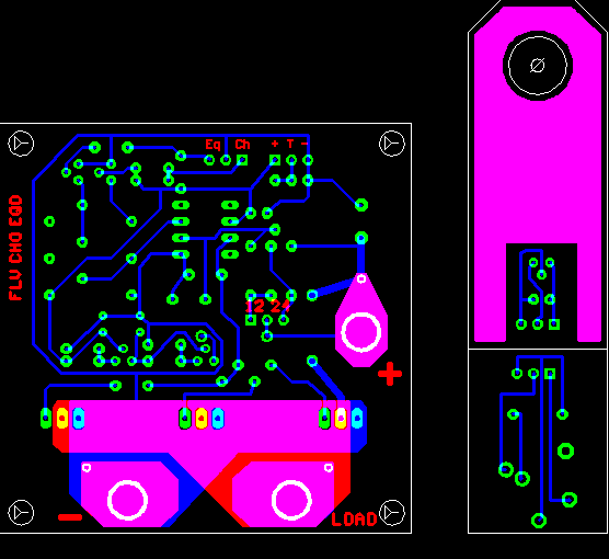


I've had pretty good luck with the high current plains on two layers as shown and it's not too difficult to make that part of the circuit two sided since, if you miss, you only have a little bit of trimming around the FET pins to do. One ounce copper is good to about 30 amps, add some copper wire to the drain and ground plains to get up to 50 amps.


The large circles are holes to drill for #10 screws and act as the high current terminals.


The mini boards on the right are for the temperature probe (upper) and receptacle for the temperature probe (lower.) Since I'm not that good at making nice boxes, I'm considering making the board a little larger and putting the miniplug receptacle and a modular phone connector for remote control directly on the main board.


The idea of the temperature probe board is that the hole at the top will allow it to go onto the screw on the plus battery terminal. The copper will conduct the heat to the temperature sensor, IC5. IC5 is a TO-92 package and should be bent over and glued onto the copper. Then the circuit area and wiring should be coated in plastic dip or equivalent to insulate it and protect it from the elements.


The voltage comparisons on the main circuit are biased with the .6 volt at 0C voltage offset of the LM61 temperature sensor. If the sensor is unplugged, R14 (on the lower mini board) will switch in and provide the equivalent offset of a 17C temperature.


The the main board layout is "modular" in that if you want to mount the FETs separately you can just cut the board above the FETs. (Then it truly is a one sided board.) Or you can cut, rotate and paste another FET area on the bottom side of the board, run a jumper across the drain or ground plain and have six on board FETs. Not sure about the drive capacity of the op amp in that case so you'd definitely want to pick FETs with low input capacitance.


Here's a placement to show where the parts are -
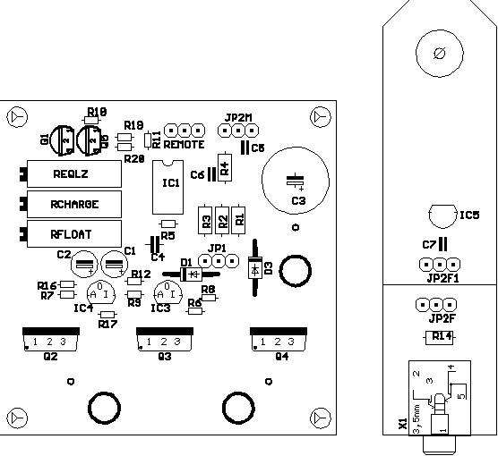


Currently, the main board is about 2.5" square.


I'll be a few weeks before I'm able to build this board so all comment pre-build are especially welcome!


Thank you very much,

 - Ed.

« Last Edit: September 08, 2007, 04:03:22 PM by (unknown) »

ghurd

  • Super Hero Member Plus
  • *******
  • Posts: 8059
Re: Deluxe++ Tiny Dump Controller
« Reply #1 on: September 08, 2007, 11:23:09 AM »
Hey Ed,

Three things.


Maybe I'm missing it. Is there a separate ground for power fets and the circuit?  Looks like the circuit ground is the same as the fet's ground. Running them through the same wire will be a problem when it gets off the bench and into the field (trust me!).


Flyback / freewheel diode.  Looks like provisions can be on board.  I didn't think it through.


`Bang-Bang'.  When does bang-bang become PWM?  No one said Morningstar is not PWM, and they claim 300Hz (?).  If this runs at 300Hz... Is it really bang-bang?


Looks good to me!

G-

« Last Edit: September 08, 2007, 11:23:09 AM by ghurd »
www.ghurd.info<<<-----Information on my Controller

elt

  • Sr. Member
  • ****
  • Posts: 328
Re: Deluxe++ Tiny Dump Controller
« Reply #2 on: September 08, 2007, 12:40:29 PM »
Thanks ghurd,


I'm not totally pleased with the ground run. The circuit is grounded with the trace that runs between the pins of R17. I did something like that on my digital dumper and it seems to work okay. I can also run the trace around the FETs on the left side and get closer to the ground terminal if you think that that would be better.


> Flyback / freewheel diode.


I don't know the terminology... is that a diode on the gate circuit? If that's a diode across the load, it's there (D3) just to the left of the plus terminal.


> `Bang-Bang'.  When does bang-bang become PWM?


I'm not sure! The width (as well as duty cycle and frequency) of the "on" signal to the gates definitely varies. I saw the characteristics predicted by some complicated math in an Intel ap-note (for one of their voltage supervisors) but it was more information than I wanted. I could see it in action though on the little breadboard when the target and reference voltages got close - the LED flickered for a part of a second, then was off for a second or so, then flickered a little, etc. To me, the "flickering" was PWM presenting a partial load to the battery. Probably though, it's just semantics. I originally called this a bang-bang controller and now I don't really see the difference. If I had to make a distinction (and what value would that have?) I guess I'd say that if the frequency is low enough for a relay I wouldn't call it a PWM though, technically, it might still be one.


Thanks again,

- Ed.

« Last Edit: September 08, 2007, 12:40:29 PM by elt »

SamoaPower

  • Sr. Member
  • ****
  • Posts: 417
Re: Deluxe++ Tiny Dump Controller
« Reply #3 on: September 08, 2007, 02:31:41 PM »
Ed,

Congratulations! It's been real neat watching you go up the learning curve on op amps with mentor Scott. It's obvious you have a flair for this sort of thing since it happened quickly. I got started before the digital era, so I had to begin with analog and go the other way. Having a grounding in both is certainly useful (necessary?).


Because an output may have a retangular waveform at some frequency doesn't necessarily mean it's PWM. The "M" part = Modulation, which requires a control input to vary the duty cycle by some intentional algorithm and is usually (but not always) closed loop. I don't think hysteresis, intentional or incidental, qualifies.


I'm curious how the final board works out.

« Last Edit: September 08, 2007, 02:31:41 PM by SamoaPower »

rossw

  • Hero Member
  • *****
  • Posts: 834
  • Country: au
Re: Deluxe++ Tiny Dump Controller
« Reply #4 on: September 08, 2007, 02:35:47 PM »
I didn't look closely at the circuit, nor analyze how it's working, but would like to offer as a suggestion, that the "flickering" you see is not PWM in any design sense, more likely that you have absolutely no hysteresis, and running the opamp at full open loop gain, any noise (mains hum induced in wiring for example, or current draw by the inverter) could/would make the thing switch on and off quickly.


If you have a 'scope available, I'd look at the output of the opamp while its in this state and see if it happens to coincide with the phase of your mains or any "bursty" load you might have.


R.

« Last Edit: September 08, 2007, 02:35:47 PM by rossw »

boB

  • Sr. Member
  • ****
  • Posts: 389
  • Country: us
    • boB
Re: Deluxe++ Tiny Dump Controller
« Reply #5 on: September 09, 2007, 03:42:16 AM »
> `Bang-Bang'.  When does bang-bang become PWM?


I think that Bang-Bang becomes PWM when the frequency is high enough

to reduce the ripple voltage, and thus the "flicker" down to a certain

level...  Sort of like an audio filters -3dB cutoff frequency.  The

larger the capacitance... the lower the frequency can be too.


I'm not sure exactly what that "amount" would be?  Maybe it ~IS~ -3dB from

fully filtered DC Voltage ?  Of course, BandBang. IS just slow PWM, as long as

it regulates to the proper average voltage, although quite a long average

time.  That's how I think of it anyway.  I wonder where that name came from

anyway ??  It seems to fit well.


boB

K7IQ


« Last Edit: September 09, 2007, 03:42:16 AM by boB »

boB

  • Sr. Member
  • ****
  • Posts: 389
  • Country: us
    • boB
Re: Deluxe++ Tiny Dump Controller
« Reply #6 on: September 09, 2007, 03:45:15 AM »
>>I wonder where that name came from anyway ??  It seems to fit well.


Maybe from the clicking or "banging" of the relay ?? If it were to be

PWM frequency, it wouldn't be a bang, but a buzz I guess.

boB

« Last Edit: September 09, 2007, 03:45:15 AM by boB »

SamoaPower

  • Sr. Member
  • ****
  • Posts: 417
Re: Deluxe++ Tiny Dump Controller
« Reply #7 on: September 09, 2007, 04:10:39 AM »
boB,

I believe I coined that term, at least here on this board, but I may have picked it up somewhere else, years past. Can't really recall. It seems I've always used it - just seems to fit its mode of operation.


http://www.fieldlines.com/story/2006/1/23/8428/49319


Can't agree about bang-bang becoming PWM. See above.


73 de AH8A

« Last Edit: September 09, 2007, 04:10:39 AM by SamoaPower »

elt

  • Sr. Member
  • ****
  • Posts: 328
Re: Deluxe++ Tiny Dump Controller
« Reply #8 on: September 09, 2007, 06:14:36 AM »
I Googled "bang bang PWM". One writer put it concisely "A PWM where only the sign of the error term is used [to determine the on-off state.]" Another was a little more fuzzy with "PWM based on hysteresis." Generally, though, bang-bang seemed to be considered to be a type of PWM. When distinction was made, it seemed to be to separate the notion of digital PWM, such as in a micro processor, from other on-off techniques.


73 de AA2MZ

« Last Edit: September 09, 2007, 06:14:36 AM by elt »

SamoaPower

  • Sr. Member
  • ****
  • Posts: 417
Re: Deluxe++ Tiny Dump Controller
« Reply #9 on: September 09, 2007, 07:31:11 AM »
Hi Ed,


"Modulation" implies some sort of varying characteristic that conveys information.


Your first quoted definition fits because of implication of potential changing sign of an error term due to some stimulus.


I would have to disagree with the second if the hysteresis is a constant.


Popular usage of the term PWM dictates some sort of active control to determine duty cycle.


It seems more a matter of semantics, so probably not very significant.


I don't claim original authorship of the term "bang-bang", as applied to controllers, other than to the point that I've used it for 30+ years.


Good luck on the project.


- - ...   ... - -

« Last Edit: September 09, 2007, 07:31:11 AM by SamoaPower »

scottsAI

  • Hero Member
  • *****
  • Posts: 884
Re: Deluxe++ Tiny Dump Controller
« Reply #10 on: September 09, 2007, 12:03:41 PM »
Ed,


Interesting side track.


Bang-bang term is very old. I have known it since early 60's.

When I was a kid, I read the term, they defined it like a furnace on/off.

The furnace is also PWM. The on off times are changed to control the temperature.

Some think the base frequency must be the same to call it PWM, not true, just so long as the on / off times are being varied its correct to call it PWM.


As a kid I got really screwed up when they switched from cps to Hz for frequency.

I must have missed the article in the mag where they defined it.


The shown controller schematic does have feedback. Not at the opamp, was redundant.

When the load is turned on, the battery and wiring have resistance. This will sag the voltage seen by the controller. When first at the trip point the off time will be longer than the on time, controlled by C4. If the battery continues to be over charged the battery voltage will continue to rise. The on time will become longer and longer to the point of staying on. PWM.


Important the load dump is larger than the worst case charging current, if the controller stays on... could over charge the battery.


Have fun,

Scott.

« Last Edit: September 09, 2007, 12:03:41 PM by scottsAI »

Nando

  • Hero Member
  • *****
  • Posts: 1058
Re: Deluxe++ Tiny Dump Controller
« Reply #11 on: September 09, 2007, 12:09:38 PM »
The circuit is a slow Bang-Bang and the ON time is defined by the time that the load is ON to bring the battery voltage below the reference and the input characteristics of the BiCmos TS921 amplifier which has a 12 volts ( 14 volts maximum limitations).

The reference is affected by the dump load current through the supply cables.


For one the supply you have it set to 9 volts, which will allow the MosFets to move their Vsat point to a higher level and may get hotter, specially when they have been operating for a while -- I recommend to increase the supply voltage to 12 volts --


The regulator producing 9 volts supply needs to be examined to define the % voltage variation due to load and or temperature, which sets as well the variations for the charging set points.


The ground of the power should be brought back from the battery -INDEPENDENT of the dump load ground to insure that you have an accurate reference that is not changed when the dump load is ON.


Also, the battery voltage for the reference needs to be brought independent to insure that you are reading the battery voltage and not the battery voltage affected by the dump load current which reduces this "true battery voltage".


If you do really want a bang-bang circuit, then you need to have a time to turn OFF the dump controller, which could be short or long depending on your needs ( for general work, I suggest around 50 to 100 milliseconds ON).


Talking about the controllers like the C family and like:


The so called low frequency PWM is a sales gimmick.


It is a bang-bang ( series) circuit around 300 HZ with PWM depending the battery voltage levels, it is fully OFF, then starts to PWM at low % and increasing this time to a 100 5 when the battery is fully charged -- so at 100 % charge the charger is fully OFF.


As a diversion charger the procedure is the Opposite, Zero time ON for below battery voltage setting, then starting to PWM at low % rates, when the battery is reaching full charge, then going 100 % when fully charged ( it is supposed that the power source has lower capabilities than the Fully ON dump Load).


Still, this type of charging systems is a Bang-bang type charger - dump controller.


For true battery profile charging the PWM should be increased to at least 100 times faster than the time that the power source is capable to vary its power ( the 300 Hz is OK for solar panels).


For wind mills, a higher rate is needed, this due to the power harvesting capability and the latency of the available power in the generator, so for this case you may need around 1500 to 3500 HZ, but to avoid noise one can increase this rate to one above human range hearing, so around 15000 up HZ.


Nando

« Last Edit: September 09, 2007, 12:09:38 PM by Nando »

elt

  • Sr. Member
  • ****
  • Posts: 328
Re: Deluxe++ Tiny Dump Controller
« Reply #12 on: September 10, 2007, 06:06:18 AM »
Hi Nando,


The ground of the power should be brought back from the battery -INDEPENDENT of the dump load ground to insure that you have an accurate reference that is not changed when the dump load is ON. Also, the battery voltage for the reference needs to be brought independent to insure that you are reading the battery voltage and not the battery voltage affected by the dump load current which reduces this "true battery voltage".


That sounds fine in theory but what does it mean in the real world? What does the extra wiring add, a little inductance and resistance? Why not just put that on the board if it's necessary. I've notice that neither the Outback nor the Xantrex controllers have separate wires... if it works for them, why not me?


Thank  you,

 - Ed.

« Last Edit: September 10, 2007, 06:06:18 AM by elt »

elt

  • Sr. Member
  • ****
  • Posts: 328
Re: Deluxe++ Tiny Dump Controller
« Reply #13 on: September 10, 2007, 06:27:35 AM »
> - - ...   ... - -


Thank you.


The digital version of my dump controller only has one button and one LED. I use a short cut for input and output since it only has to do numbers. I'll likely do the same when I attempt the charge controller:


  1. = .
  2. = ..
  3. = ...
  4. = ....
  5. = -
  6. = -.
  7. = -..
  8. = -...
  9. = -....
  10. = --


Send rate is about 3 digits in 5 seconds; equivalent to about 9 WPM.


On input, you can do either. For example, if you're not sure of your timing you can press the button six times for "6" but it will also take a "long" press and a "short" press. Timing is fixed but allows a lot of leeway. A dit is between 30 and 250 milliseconds, a dah is 260 ms to 1.99 seconds and 2 seconds or longer is a "cancel."


_.. ...


 Ed.

« Last Edit: September 10, 2007, 06:27:35 AM by elt »

ghurd

  • Super Hero Member Plus
  • *******
  • Posts: 8059
Re: Deluxe++ Tiny Dump Controller
« Reply #14 on: September 10, 2007, 07:47:26 AM »
The control circuit is looking at the battery voltage, right?

Say for the ground wire, you have 8' (2 in the battery box, 2 horizontal, and 4' up to the controller?) of #6 wire.  When the circuit decides to dump those 50A... what happens to the voltage the controller THINKS is the battery voltage?


I won't pretend to understand the intricacies of your circuit. Mine is constantly looking at the battery voltage, not related to time.


Real World.  I wanted my controller Idiot Proof, uh, I mean `able to survive very adverse conditions'.

The worst case I could come up with, and no cap, had it running slightly under 5 MHz. The duty cycle was Very short, not long enough to dump the incoming power, so while running at 5MHz the battery was still overcharging.


Most of the problem was the control circuit and dump load on the same undersized wire.  The instant the load came on, the voltage drop in the wire told the controller that the battery voltage was low, so it shut the load off. The instant the load shut off, the battery voltage was too high...

Separate wires and the 10uF cap kept it down to my target of 100Hz max worst case (fast enough for the intended use, while keeping the fets time spent linear/switching to a small percentage).


Leave them connected if you want, but please, add a pad for a separate ground wire for the circuit.  It will keep the option open.


A flyback diode is a reverse connected high speed diode, in parallel with an inductive load.  It takes the voltage spike then the load is switched off, protecting the circuit.  Cheap insurance.  Most power resistors are inductive.  Many relays include one in the case.  

http://www.kpsec.freeuk.com/components/relay.htm#protect


G-

« Last Edit: September 10, 2007, 07:47:26 AM by ghurd »
www.ghurd.info<<<-----Information on my Controller

BigBreaker

  • Sr. Member
  • ****
  • Posts: 302
Re: Deluxe++ Tiny Dump Controller
« Reply #15 on: September 10, 2007, 09:14:53 AM »
Power resistors are often coiled wire (nichrome perhaps?), so yes - much more inductive than straight wire or a cylinder of resistive media.
« Last Edit: September 10, 2007, 09:14:53 AM by BigBreaker »

elt

  • Sr. Member
  • ****
  • Posts: 328
Re: Deluxe++ Tiny Dump Controller
« Reply #16 on: September 10, 2007, 12:53:59 PM »
Say for the ground wire, you have 8' [...] When the circuit decides to dump those 50A.. what happens


So you're going to make me do the math, huh? Okay, for 8 feet each way of #6 wire the the battery voltage will be a little higher than the target on the dump controller:


+.200v @ 50 amps

+.125v @ 40 amps

+.072v @ 30 amps

+.032v @ 20 amps

+.008v @ 10 amps

+.000v @  0 amps


So, yes, the battery voltage will be a little high while excess power is being produced by the mill. Of course, when the mill slows down the controller will bring the excess volts back on target. Arguably, a little excess charge might not be a bad thing but I do hate to see it as a side effect of the wiring. I can think of it another way: My mill appears to furl at about 33 amps. The batteries charging (or floating) at .08 volts too high a voltage is no worse than 3C or 5F degree error in temperature compensation... I don't think it's enough to loose sleep over.


On the other hand, I don't see a down side to providing for another set of wires running to the battery to get the reference voltage there...


> Separate wires...


... as you suggested.


> and the 10uF cap


The .1 uF cap shown is a leftover from the .5 amp load on the breadboard. ScottAI has previously suggested that I'll likely need a 47uF in there for a large load.


> A flyback diode [...] in parallel with an inductive load.


Yes, that's D3.


Thank you!

 - Ed.

« Last Edit: September 10, 2007, 12:53:59 PM by elt »

ghurd

  • Super Hero Member Plus
  • *******
  • Posts: 8059
Re: Deluxe++ Tiny Dump Controller
« Reply #17 on: September 10, 2007, 01:36:50 PM »
I totally missed the purpose of D3.

I don't think it is enough to loose sleep over either.  As long as it doesn't cause problems.

G-
« Last Edit: September 10, 2007, 01:36:50 PM by ghurd »
www.ghurd.info<<<-----Information on my Controller

elt

  • Sr. Member
  • ****
  • Posts: 328
Re: Deluxe++ Tiny Dump Controller
« Reply #18 on: September 15, 2007, 05:52:37 PM »
I made a some changes to the circuit; hopefully improvements -


http://www.otherpower.com/images/scimages/6527/tiny_29s.gif


Primarily, I moved the temperature compensation to the reference-voltage (negative) side of the op amp... The change allows the circuit to get the same compensation for the three voltage modes (float, charge, equalize) and for all three systems voltages (12v. 24v. 48v.) Before, it was close but not exact. The voltages and temperature compensation shown is what the Trojan web site specs for their batteries. The three trim pots will allow setting the voltage levels to other values for other batteries and chemistries. Changing the battery voltage divider ratio (on the positive side of the op amp) allows for other temperature compensation values. (The 1 to 2.58 ratio is for 30mv per degree C.)


I moved the resistors from the on-off-on switch to the "remote" connection side of the float/charge/equalize selection. This gives priority to the switch for manual control. The switch should be put in the float (off) position for remote control.


I put connectors and a switch across the top of the board. My opinion is that it's easier to deal with on board receptacles than wiring to off board ones. The beauty is that if you feel otherwise, you can wire external receptacles to the on board footprints.


Also, per ghurd's suggestion, I added a little header for getting the battery voltage separate from the dump load. Implementation is in the board layout; the way I did is that you cut a batt+ and GND trace near the big cap to separate the two power sections.


I've etched a board -


The connectors and switch make the board a little bigger, now 2.5" x 3"


And sent off some requests for samples. Once I know what samples are coming I'll order the rest of the parts and populate the board.


Thanks for all the help!

- Ed.

« Last Edit: September 15, 2007, 05:52:37 PM by elt »

elt

  • Sr. Member
  • ****
  • Posts: 328
Re: Deluxe++ Tiny Dump Controller
« Reply #19 on: September 18, 2007, 04:49:29 PM »
I built the temperature probe today!


National wouldn't sample (for free) the LM-19 I designed for but they would sample some little surface mount devices. I used to be afraid of SMDs but with practice I've become "fair" at soldering them if the pitch isn't too fine... the price was right so I went ahead and ordered some.  


I decided to "dead bug" the SMD to the board designed for the LM-19 rather than etch another board. I think that the procedure is even easer than soldering SMDs to pads because the scale is a lot larger... The strategy is to use a razor knife to cut the copper into "islands" that the pins on SMD will span. Then tin the islands, put the SMD down and reheat the solder to sink the pins into the solder. Then, in this case, I ran wires from the TO-92 footprint to the islands (which now act like really big pads!)


My camera doesn't close close-ups so I added a little drawing to show how the SMD is "wired." (The sensor has five pins that allow four programmable gains. The connections show yield -10.6mv/C. I'll need to redo the voltages on the main board but do big deal...)


Once tested, I potted the parts in epoxy, I think this is important because you don't want the SMD to pop off because of board flexure. Once that set, I painted the back end with black rubber. I'll go back over that again with red to remind myself that I want to put the sensor on the positive terminal of a battery (which, I've read, tracks the internal temperature of the battery better than the negative terminal or the outside of the case.)


You can see the LED glowing; that gives a visual indication that the the probe is connected and powered.


In hindsight, I'm pleased that I though ahead enough to allow for strain relief but I sure was stingy with the pads for the wire coming to the board; I'll definitely make those pads a little larger and farther apart if I have to make another probe.

- Ed.

« Last Edit: September 18, 2007, 04:49:29 PM by elt »