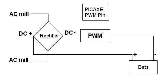
I think a problem with my system is that the wind mill sees too much battery. I could add a massive resistor between wind mill and battery, replacing the PWM box in this picture:

with a big resistor. That would generate heat which I could use to heat up something, using it like a dump load. Adding a resistor like this can improve aerodynamics, but the battery gets less of a charge. Instead, I'm trying to see if I can use PWM to mask the battery's influence on my wind mill's RPM, but I need a sensor. So here's my next crazy idea.
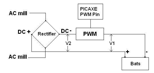
I think voltage from a PWM circuit can be split up like this:

V1 is the voltage seen by the battery because it's connected to the wind mill, through the PWM circuit. V2 is the voltage between rectifier and PWM. To get the battery to charge, V1 has to be bigger than battery voltage so I need to know V1. Here's the catch (drum roll ...). If I put a voltmeter at V1, all I get is battery voltage. I can't measure V1 directly, because it gets swamped by battery voltage. I'm trying to use V2 to get V1.
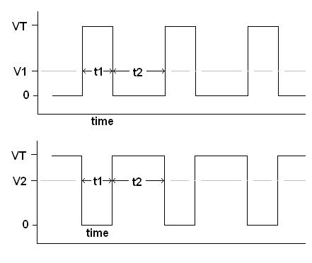
Here's the classic PWM diagram:

The battery should see a charge from the wind mill for a time t1, and should see nothing for a time t2 (top graph). The bottom graph is what should be left over between rectifier and PWM circuit. If my math is right and I measure V2, can I get V1 from:
V1 = D * V2 / (1 - D)
where D is the duty cycle.
Disclaimer: This is only a theoretical diagram and any correlation with reality is purely coincidental. An oscilloscope would probably show some nasty dips and spikes and harmonics.
Mau