Author Topic: Got PWM: need a sensor.  (Read 1880 times)

0 Members and 1 Guest are viewing this topic.

bigkahoonaa

  • Jr. Member
  • **
  • Posts: 57
Got PWM: need a sensor.
« on: October 18, 2007, 04:27:41 AM »
I think a problem with my system is that the wind mill sees too much battery.  I could add a massive resistor between wind mill and battery, replacing the PWM box in this picture:


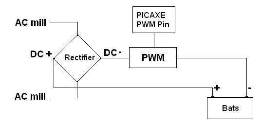
with a big resistor.  That would generate heat which I could use to heat up something, using it like a dump load.  Adding a resistor like this can improve aerodynamics, but the battery gets less of a charge.  Instead, I'm trying to see if I can use PWM to mask the battery's influence on my wind mill's RPM, but I need a sensor.  So here's my next crazy idea.  


I think voltage from a PWM circuit can be split up like this:


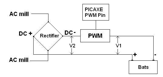
V1 is the voltage seen by the battery because it's connected to the wind mill, through the PWM circuit.  V2 is the voltage between rectifier and PWM.  To get the battery to charge, V1 has to be bigger than battery voltage so I need to know V1.  Here's the catch (drum roll ...).  If I put a voltmeter at V1, all I get is battery voltage.  I can't measure V1 directly, because it gets swamped by battery voltage.  I'm trying to use V2 to get V1.


Here's the classic PWM diagram:


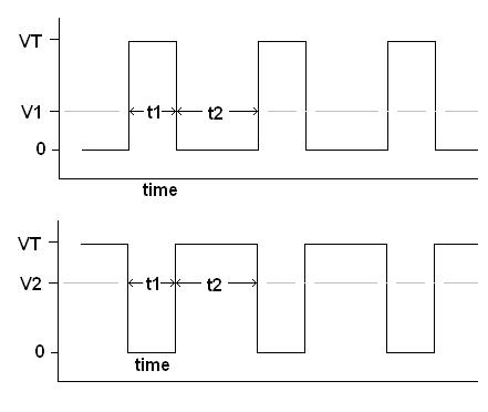
The battery should see a charge from the wind mill for a time t1, and should see nothing for a time t2 (top graph).  The bottom graph is what should be left over between rectifier and PWM circuit.   If my math is right and I measure V2, can I get V1 from:


V1 = D * V2 / (1 - D)


where D is the duty cycle.  


Disclaimer:  This is only a theoretical diagram and any correlation with reality is purely coincidental.  An oscilloscope would probably show some nasty dips and spikes and harmonics.


Mau

« Last Edit: October 18, 2007, 04:27:41 AM by (unknown) »

Rob Beckers

  • Full Member
  • ***
  • Posts: 146
  • Country: ca
Re: Got PWM: need a sensor.
« Reply #1 on: October 18, 2007, 07:12:57 AM »
Hi Mau,


Normally the voltage (V1 in your diagram) or AC frequency (which is proportional to rotor RPM) is used together with a lookup table that is specific for the wind turbine to present the proper load to the turbine. That way the PWM controller won't try to load the turbine too much at low RPM or voltage (V1). That also alows you to do MPPT for wind. Using the rotor RPM is more accurate than using voltage.


-RoB-  


        Solacity Inc.

        Phone: (613) 686-4618

        Fax:   (613) 686-4622


-- This message was entirely  written using recycled electrons --

  All about the 6 kW Scirocco wind turbine at www.solacity.com

    Join the Green Power Talk forum at www.greenpowertalk.org

-----------------------------------------------------------------

« Last Edit: October 18, 2007, 07:12:57 AM by Rob Beckers »

elt

  • Sr. Member
  • ****
  • Posts: 328
Re: Got PWM: need a sensor.
« Reply #2 on: October 18, 2007, 08:53:19 AM »
Hi Mau,


Your circuit is going to me unregulated so V1 _ is _ the battery voltage and that's that. What you'll see going into the battery is "amps." Battery amps times V1 equals mill amps times V2 (if your converter were 100% efficient.) So go ahead and use the number you get measuring V1.


As far as sensors go, google the board for "current sensor" (with quotes) or shunt or "hall effect" and you'll have lots of info available.


Hope that helps,

- Ed.

« Last Edit: October 18, 2007, 08:53:19 AM by elt »

bigkahoonaa

  • Jr. Member
  • **
  • Posts: 57
Re: Got PWM: need a sensor.
« Reply #3 on: October 18, 2007, 11:28:33 AM »
Hi RoB


I forgot I could use RPM.  Could be a pain to measure accurate RPM at low RPM.  Thanks for the idea.


Mau

« Last Edit: October 18, 2007, 11:28:33 AM by bigkahoonaa »

BigBreaker

  • Sr. Member
  • ****
  • Posts: 302
Re: Got PWM: need a sensor.
« Reply #4 on: October 18, 2007, 03:18:16 PM »
No power at low RPM anyhow.
« Last Edit: October 18, 2007, 03:18:16 PM by BigBreaker »

David HK

  • Hero Member
  • *****
  • Posts: 509
  • Country: hk
Re: Got PWM: need a sensor.
« Reply #5 on: October 18, 2007, 04:16:28 PM »
Hello Mau,


Go to this web site because it may be of some assistance to you.


http://www.thebackshed.com/Windmill/PicLog.asp


David HK

« Last Edit: October 18, 2007, 04:16:28 PM by David HK »

Rob Beckers

  • Full Member
  • ***
  • Posts: 146
  • Country: ca
Re: Got PWM: need a sensor.
« Reply #6 on: October 19, 2007, 07:24:50 AM »
There are frequency sensors (which gives you a signal proportional to RPM) in IC form. The type numbers escape me right now, a little Internet search should find them. That should provide an easy way to get that information into your micro-controller.


-RoB-


-- This message was entirely  written using recycled electrons --

  All about the 6 kW Scirocco wind turbine at www.solacity.com

    Join the Green Power Talk forum at www.greenpowertalk.org

-----------------------------------------------------------------

« Last Edit: October 19, 2007, 07:24:50 AM by Rob Beckers »

elt

  • Sr. Member
  • ****
  • Posts: 328
Re: Got PWM: need a sensor.
« Reply #7 on: October 19, 2007, 08:28:18 AM »
I've been wondering this myself, couldn't you just put something like a zener on one phase and count pulses at a uP input pin?


- Ed.

« Last Edit: October 19, 2007, 08:28:18 AM by elt »

Kilted

  • Newbie
  • *
  • Posts: 11
Re: Got PWM: need a sensor.
« Reply #8 on: October 30, 2007, 10:32:16 PM »
To get rpm why not use a tachometer like: http://www.servo-tek.com/ get one that has 20v/1000rpm then do a voltage divider, comparater.  


Current eBay sale http://cgi.ebay.com/4-Servo-Tek-DC-Tachometer-Generator-20-8-Vlts-1K-RPM_W0QQitemZ170164311126QQihZ0
07QQcategoryZ78195QQssPageNameZWDVWQQrdZ1QQcmdZViewItem


Sorry I just had to point out an obvious solution that seems to have been missed.


--  Brandy

« Last Edit: October 30, 2007, 10:32:16 PM by Kilted »