Author Topic: 17' turbine in West Virginia  (Read 10995 times)

0 Members and 1 Guest are viewing this topic.

dlenox

  • Sr. Member
  • ****
  • Posts: 352
    • PowerDashboard monitoring/logging software for RE systems
17' turbine in West Virginia
« on: October 20, 2007, 11:38:35 PM »
Background:

I wanted to build a 2-3kw wind turbine and after finding the OtherPower.com website ran across their 17' one which looked like what I had been wanting.


My wife and I live in NE part of rural West Virginia on about 7 acres on top of a mountain ridge with an elevation of 3000'. From our property we have a panoramic view of about 50miles in almost a 270 degree radius. There is always wind here and it was the logical choice for me to make and install my wind turbine.


I did not want a tower with guy wires but instead wanted a free standing unit.


I required a retractible 10' tower stub to essentially bring the turbine down to the top of the tower for maintenance. In addition I needed to build a davit crane which will be permanently be mounted on top of the tower in case I need to remove the turbine.


The yaw bearing and components will be considerately 'beefed up' from the OtherPower.com 17' turbine. Structurally it is closer to that used for the 20' one.


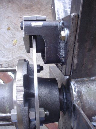
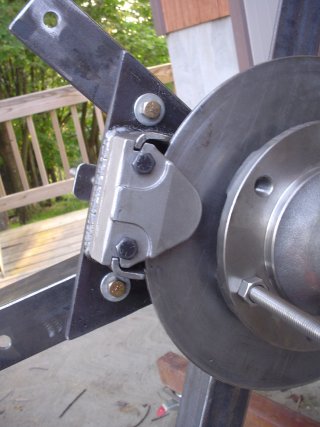
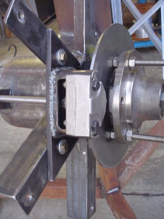
A positive stopping mechanism will be used as my area is prone to high winds, I will be using a mechanical disc brake caliper that is engaged using a 12v dc linear actuator. This provides positive stopping and release of the brake pads from the brake rotor, unlike hydraulic calipers.


A complete project build website has been made which has far more detail that that which follows, it can be found HERE.


Here is progression of building and flying my 17' wind turbine:


4.27.07 Matt Sherald from Pimby (Power In My Back Yard) came by to do a quick site survey. Pimby has been working on a number of local projects, a lot of commercial wind farms and Matt's partner Jeff Melnick is a master electrician, they both seem very pleasant and quite capable.


Lots of research follows.


  1. 14.07 Talked with Dan Simmonds from AN Wireless, and ordered up an engineering study to see if their HD-70 would work for my application. AN Wireless makes a 3-sided lattice tower, it is not able to be manually lowered and requires a crane for installation.
  2. 26.07 I receive engineering study from\ AN Wireless and their tower suits my application! So I place order for HD-70 (70' lattice tower), step bolts, 3/8" life line system, dual grounding system and 6 mounting brackets for the plates to hold the stub.
  3. 20.07 Picked up my tower sections using my trailer and brought them home.
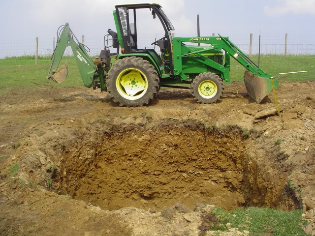
  4. 4.07 Dug out the hole for the tower foundation using my back-hoe


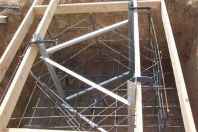
Made up the rebar framework for the tower foundation using layout specified by AN Wireless engineers. And 80' long dug trench for conduit from foundation to my garage, laid 2 separate runs of 1-1/2" pvc conduit.


8.13.07 Installed rebar and lower tower section into foundation pit and poured 12yds of 3000psi concrete with the help of my good friend Paul Schreiner of PS Composites.


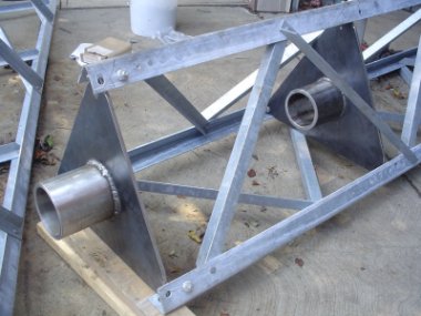
8.18.07 Picked up most of steel necessary to fabricate yaw bearing and tail.


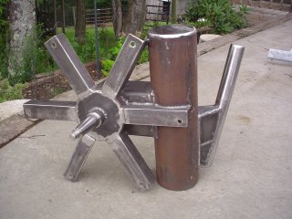
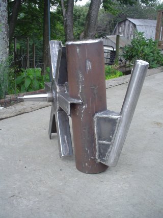
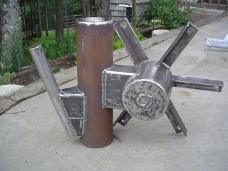
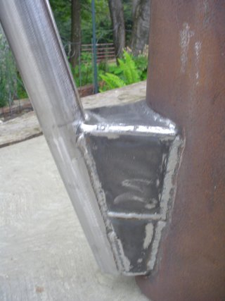
8.19.07 Basically finished with yaw bearing and tail.


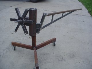
8.24.07 Mount a disk brake onto the yaw bearing for stopping the turbine.


8.25.07 Fabricate the plates that hold the stub onto the tower.


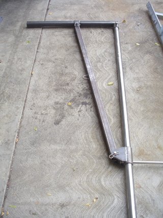
8.26.07 Fabricate the basic davit crane for mounting onto the tower.


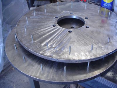
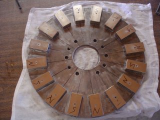
9.4.07 Fabricate the 18" diameter rotors, I put 3/16" pins in where each magnet will be mounted, the magnets I purchased were 1-1/2" x 3" x 3/4" with a 3/16" hole in the center.


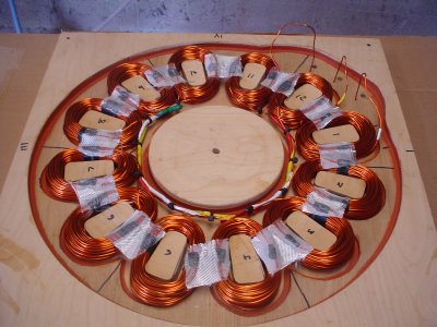
9.6.07 Completed coil winder got all 12 coils made. Completed building stator mold. Went over to PS Composites. and Paul and I used a special high temperature epoxy resin to make the stator.


9.7.07 Made up some work platforms for the tower and mounted brake winch for the davit crane.


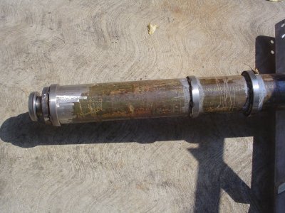
9.8.07 Fabricated the mount on top of the stub for the 1932 Ford Model A thrust bearing. Also fabricated collars for guiding the yaw bearing on the stub.


  1. 9.07 Completed fabricated the remaing portions of the davit crane.
  2. 15.07 Fabricated a pulley system for guiding the cable from the hand brake winch to the bottom of the davit crane.
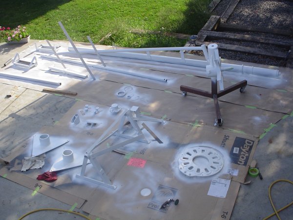
  3. 16.07 Using epoxy primer I primed the yaw bearing, stub plates and shaft, stator and all tower modifications.


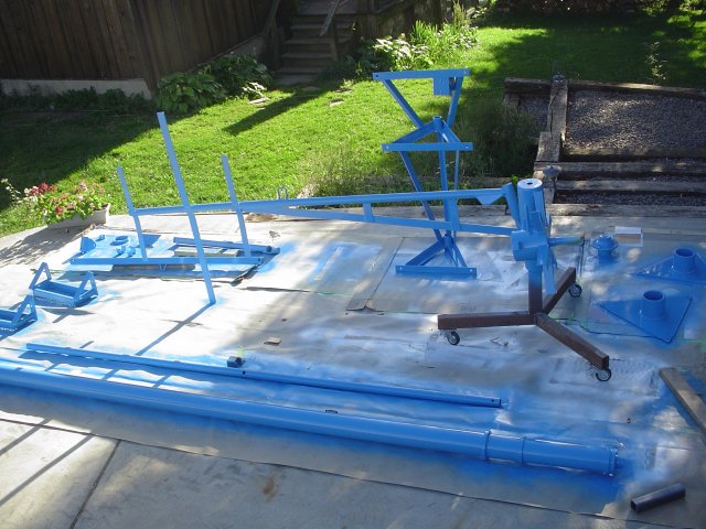
9.21.07 Applied cobalt blue polyurethane enamel paint to all primed components.


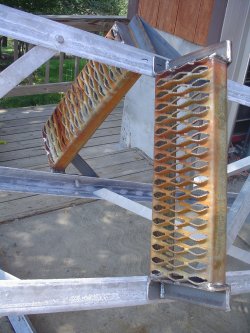
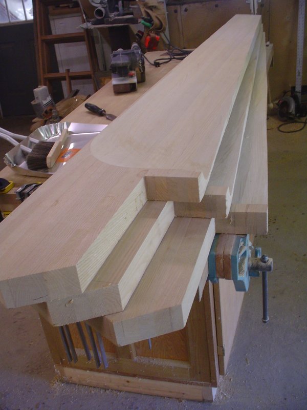
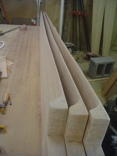
  1. 22.07 Planed up planks of sassafras and cut into 2-1/2" boards enough to make the 3 blades.
  2. 23.07 Glued up the 3 blade blanks and planed them down to 2-1/4" thickness.
  3. 29.07 Cut the faces of the blades and set the pitch angle.


10.4.07 Completed the back sides and leading edges of the blades.


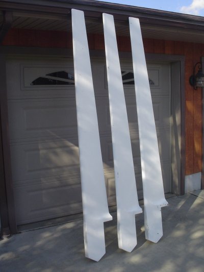
10.6.07 Completed applying 6oz fiberglass cloth to all blades, sanded and epoxy primered them. Made the 30" diameter blade hubs from 1/4" steel plate.


10.7.07 Put all magnets onto rotors, used polyester resin onto both rotors. Cut out tail vane from 1/2" plywood


  1. 15.07 Made mount for linear actuator onto the yaw bearing. This will be used to engage/release the disc brake. Began assembly of the turbine rotors and stator, fabricate some aluminum spacers to space the rotors apart.
  2. 17.07 Crew from Pimby arrive and begin assembling the tower sections in field.
  3. 18.07 Purchased S/O cable to run from turbine through the stub to the first electrical box. Got electric winch mounted to tower, this will be used to raise/lower the stub as well as it is moveable to the davit crane for raising/lowering from top of tower to ground.


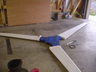
Blades mounted onto the steel hubs.


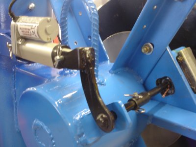
Fabricated linkage to go from linear actuator to the disc brake caliper. Yaw bearing assembly is now complete.


10.19.07 Tower erection day! Very large commercial crane was commissioned to raise tower, It was deemed too windy to mount the blades and tail section so just the yaw bearing was placed on top of the stub.


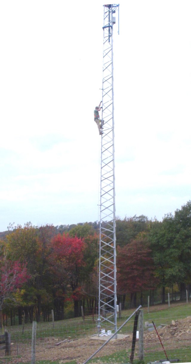
Tower being climbed for the first time


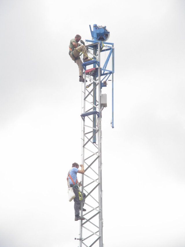
Yaw bearing installed on tower stub


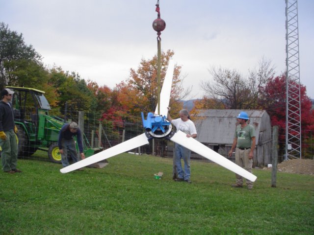
Balancing the blades


« Last Edit: October 20, 2007, 11:38:35 PM by (unknown) »

dynaman

  • Newbie
  • *
  • Posts: 25
Re: 17' turbine in West Virginia
« Reply #1 on: October 20, 2007, 06:36:00 PM »
Beautiful work. Look forward to reading about its performance
« Last Edit: October 20, 2007, 06:36:00 PM by dynaman »

harrie

  • Sr. Member
  • ****
  • Posts: 365
Re: 17' turbine in West Virginia
« Reply #2 on: October 20, 2007, 09:17:47 PM »
Very neat work, I can see you have given it alot of thought. I hope the brake holds up for you, with 8.5 foot blades, you will have alot of tourqe at the pads!! Good Luck
« Last Edit: October 20, 2007, 09:17:47 PM by harrie »

jmk

  • Hero Member
  • *****
  • Posts: 603
Re: 17' turbine in West Virginia
« Reply #3 on: October 20, 2007, 11:44:15 PM »
 You sure do excellent work! All of your fabrication looks great. I find it hard to believe that tower can hold up to the load. I can't imagine it holding up to a 70 mph wind? Maybe it's just me? Does it move around at the top when your up there? If it were me I think I would at least have the top guyed to where you could hook them up if needed to. I can't wait to hear the performance. It looks like you will get good wind.    
« Last Edit: October 20, 2007, 11:44:15 PM by jmk »

chadking

  • Jr. Member
  • **
  • Posts: 64
Re: 17' turbine in West Virginia
« Reply #4 on: October 21, 2007, 01:47:26 AM »
Wow!  Good work! Fabrication and setup look excellent.  Keep us updated with pics of the prop installed, and results of the venture.  
« Last Edit: October 21, 2007, 01:47:26 AM by chadking »

FishbonzWV

  • Sr. Member
  • ****
  • Posts: 280
Re: 17' turbine in West Virginia
« Reply #5 on: October 21, 2007, 06:27:22 AM »
Dan,

Nice professional work!

I was hoping you would keep the board updated on your progress.

If you would like to show it off when you get it finished I've got contacts at the Charleston newspapers.


Fishbonz

« Last Edit: October 21, 2007, 06:27:22 AM by FishbonzWV »
"Put your brain in gear before you put your mouth in motion"
H.F.Fisher 1925-2007

RobC

  • Full Member
  • ***
  • Posts: 180
Re: 17' turbine in West Virginia
« Reply #6 on: October 21, 2007, 09:08:18 AM »
 I hope you plan on guy wires at the top of your Tower. I can tell you from experience that it's not much fun to find everything laying on the ground. Great workmanship nice machine. RobC
« Last Edit: October 21, 2007, 09:08:18 AM by RobC »

Mary B

  • Administrator
  • SuperHero Member
  • *****
  • Posts: 3191
Re: 17' turbine in West Virginia
« Reply #7 on: October 21, 2007, 11:10:55 AM »
AN towers are designed to hold large loads. Many of the lattice type cell towers are AN and those antennas present a huge windload.
« Last Edit: October 21, 2007, 11:10:55 AM by MaryAlana »

RobC

  • Full Member
  • ***
  • Posts: 180
Re: 17' turbine in West Virginia
« Reply #8 on: October 21, 2007, 02:13:09 PM »
In my opinion comparing a radio antenna to 17 ft wind turbine in terms of wind load is like comparing a riding lawn mower to 50hp tractor. It also appears that the center line of the turbine maybe a little to close to the tower for good furling but I can't really tell from the pictures. But what do I know I've  been wrong before. RobC
« Last Edit: October 21, 2007, 02:13:09 PM by RobC »

dlenox

  • Sr. Member
  • ****
  • Posts: 352
    • PowerDashboard monitoring/logging software for RE systems
Re: 17' turbine in West Virginia
« Reply #9 on: October 21, 2007, 03:03:52 PM »
Guys,


Before I purchased the tower I paid the engineers to do an engineering study.


According to their results (has engineering stamp on it), that the tower with my setup will be good up to 90mph winds. With the assumption that the ice load is within some tolerances.


I have not climbed the tower yet but when erected there were 2 men on top and the top of the tower barely appeared to move with the available wind.


Dan

« Last Edit: October 21, 2007, 03:03:52 PM by dlenox »

dlenox

  • Sr. Member
  • ****
  • Posts: 352
    • PowerDashboard monitoring/logging software for RE systems
Re: 17' turbine in West Virginia
« Reply #10 on: October 21, 2007, 03:14:05 PM »
Thanks for all the positive comments.  The tower appears to be super strong, I have not climbed it yet but will when we can get the blades and tail assemblies winched up and installed.


Since my tower is not 'lowerable' I put a ton of thought into being 70' in the air as well as maintenance at that height...  I could not afford to have a huge crane come back, and knew that eventially I would need to bring the turbine down for some service so hence the davit crane that I designed/built/installed onto the tower.


Today I worked on setting the blade balancing weights.


I removed the temporary weights that I used to balance the blades with and weighed them. They both were with 1/2 oz of each other. When I made up the blades the 3rd one that I cut I knowingly left more material along both the back side and the leading edge. (Eventially Paul Schreiner from PS Composites will take the blade and make a mold from it). Those of you that have seen my Vortex project know that I used this method to fiberglass on mounting plates onto the chassis. The principal is simple you take a steel plate fill it with holes, next you mount it with glass matt between the plate and the surface. Then you put one (or more) layers of matt over the surface, pushing the matt down where the holes are and then finally put a cover of 6oz glass cloth. The pushed down matt in all of the holes bond to the matt that is below the plate and give you a super strong hold!


The total weight needed to be added was 1 lb 3 oz to the remaining two blades. So I took a couple of pieces of 1/8" thick steel plate and approximated the size and cut it out in the basic shape of the blade, slightly tapered on one edge. I did a pretty good job of approximating it as it came out to be 1.5 lbs, right on target! I filled both of them with a series of 1/2" holes and tapered all of the outside edges.


Once all the holes were in I put a slight bend in along the length just after the first set of holes as they were positioned to start up to the leading edge of the blade. Here is a picture of the final plates, they came in at a hair under 1lb:


The reason that I made them slightly lighter is that I was going to add beteen 3-4oz of resin and I wanted the total weight added to be my target weight. The entire surface of the blade needed to be sanded to remove the epoxy paint where I was adding the patch, you have to get down to the subsurface layer of glass cloth for best adhesion.


Here is what the plate looks like where I will be mounting it:


I added some white pigment to the resin so that I did not have to paint when done, in addition I added some milled fibers to help thicken the resin so that it would not run off and create voids.


Here is a picture with the layers of matt and cloth added and waiting for the resin to go off:


Before the resin took a final set I used a sharp knife and trimmed off the bulk of the excess along the leading and trailing edges. Once the resin hardened I lightly sanded around the perimeter to get a smooth finish. Here is what the blade weight looks like when finished:


Now the blade assembly is all ready to be put into service.

« Last Edit: October 21, 2007, 03:14:05 PM by dlenox »

dlenox

  • Sr. Member
  • ****
  • Posts: 352
    • PowerDashboard monitoring/logging software for RE systems
Re: 17' turbine in West Virginia
« Reply #11 on: October 21, 2007, 03:22:24 PM »
Rob,


Right now the top stub is retracted!  Once blades and tail assemblies are in place the stub gets raised 10' above where you see the turbine at in the pictures.


I needed a telescoping stub as maintenance would have been impossible otherwise.  There is an electric winch attached which is used to raise/lower the stub down to the top of the tower.


Dan

« Last Edit: October 21, 2007, 03:22:24 PM by dlenox »

dlenox

  • Sr. Member
  • ****
  • Posts: 352
    • PowerDashboard monitoring/logging software for RE systems
Re: 17' turbine in West Virginia
« Reply #12 on: October 21, 2007, 03:28:41 PM »
Thought that I would clarify where I put the weights onto the blades.


Forgot to mention that the blade weights were put on the 'back side' of the blades and not on the front side (where the blade pitch is).  This way they should distrupt the air flow as little as possible.


Dan

« Last Edit: October 21, 2007, 03:28:41 PM by dlenox »

Mary B

  • Administrator
  • SuperHero Member
  • *****
  • Posts: 3191
Re: 17' turbine in West Virginia
« Reply #13 on: October 21, 2007, 06:02:04 PM »
Cell phone antenna arrays measure in the hundreds of square feet. And many weigh upwards of 2,000 pounds. They are not a small antenna!
« Last Edit: October 21, 2007, 06:02:04 PM by MaryAlana »

scorman

  • Full Member
  • ***
  • Posts: 181
balance weights placement
« Reply #14 on: October 21, 2007, 06:36:40 PM »
Dan,

"they should distrupt the air flow as little as possible" ????


Do my eyes deceive me, or did you place the weight at the tip end of the blade?


If it is, backside or front side is irrelevant ...the premise of an airfoil is a "smooth" transition at all points ...any disruption will add significant drag and probably noise as well


BTW, I did check out your website and saw the specifics of your blade profile and planform ...your numbers come fairly close in dimension and weight to what I am building for a 18' turbine ( I am gluing up sycamore with Titebond III)


Stew Corman from sunny Endicott

« Last Edit: October 21, 2007, 06:36:40 PM by scorman »

dlenox

  • Sr. Member
  • ****
  • Posts: 352
    • PowerDashboard monitoring/logging software for RE systems
Re: balance weights placement
« Reply #15 on: October 22, 2007, 08:26:48 AM »
Stew,


Ok, I am showing my ignorance here.


I did not do any static balancing, only dynamic with the blade assembly mounted on the turbine.


The profile of the weights closely matches the profile of the back of the blade.


I understand that the tips of the blades rotate faster than the root does, what would the potential problems be in the placement of the weights as I have them?


I have searched and did not come up with anything that showed how to balance blades.  It is not too late for me to change the balancing if necessary.


Dan

« Last Edit: October 22, 2007, 08:26:48 AM by dlenox »

dlenox

  • Sr. Member
  • ****
  • Posts: 352
    • PowerDashboard monitoring/logging software for RE systems
Re: balance weights placement
« Reply #16 on: October 22, 2007, 10:28:07 AM »
Ok, after some investigation I think that I can answer my own question.


Drag at the tips can cause fluttering, which translates to vibration as well.


It is more important to put the weight nearest the center and leave the airfoil at the tips clean.


I may take off the heavy blade and rework to get it more in line with the other 2, reglass it and rebalance again.


Dan

« Last Edit: October 22, 2007, 10:28:07 AM by dlenox »

scorman

  • Full Member
  • ***
  • Posts: 181
Re: balance weights placement
« Reply #17 on: October 23, 2007, 11:40:20 AM »
Dan,

Yes, it looks like you answered your own question before I had a chance to respond.


Most people simply drill a plug in the non-performing root section of lighter blades , and fill it with lead or such.


"The total weight needed to be added was 1 lb 3 oz to the remaining two blades"


IMHO, in your case with the one heavy blade, you could drill a hole (or two?) with a 1" spade bit in the root within the mounting plate area, until you get the right weight and fill it with styrofoam plug before reglassing?


I have recently gotten a digital scale which goes up to 50# to statically  balance/weigh each blade. If one blade sticks out an extra 1/3inch, it could cause dynamic unbalance ..check that too! ...but these larger rotors aren't spinning that fast ie Dave B's 18 footer only goes to 250rpm at 20mph w/TSR= 5.5


If you spin it by hand when rotor is vertical and the rotor stops at random orientations ..that is good enough.


As far as "flutter" you mention, there was an article about testing of wind tunnels ( not testing WITH wind tunnels) and they could measure a loose piece of scotch tape on the inside wall of the tunnel ...so, you don't want to screw up a perfectly good airfoil profile with any "lumps"


BTW, I am very impressed with your whole build project... first class!


Stew Corman from sunny Endicott

« Last Edit: October 23, 2007, 11:40:20 AM by scorman »

dlenox

  • Sr. Member
  • ****
  • Posts: 352
    • PowerDashboard monitoring/logging software for RE systems
Re: balance weights placement
« Reply #18 on: October 23, 2007, 12:57:49 PM »
Mitcamp,


I guess that I have a lot to thank you for in making the notation about the position of my weights - THANKS!


Initially I think that I underestimated the importance of having consistant weight and shape, I see now just how important to the successful operation of the turbine that it is.  When I glassed the blades I forgot all about the one being different and should have addressed it then, but with the huge list of things to finish up before erection day I forgot to.


Since I have almost a week till the blades get mounted onto the turbine, I will be removing the heavy blade, reshaping the backside/leading edge area to bring it in line with the other two, and then reglassing it.  As well as removing my attempt to balance the other two blades and get their airfoils back to previous shape.  It's only about 1/2 days work to fix.


After more research I found an article here on fieldlines titled How To Balance Wind Turbine.  I am doubtful for the size of the blades that I have that running a center string to do static balancing is viable as it has to hold about 110lbs, perhaps a heavy steel wire might work in my case, and will try that


I ordered up another hub with stub shaft that I can use to connect the entire blade assembly and perform some dynamic balancing off the turbine.  Probably use the bucket of my tractor for this so that I can get it high enough without lifting the assembly manually...


I can certainly see where a digital scale would come in handy all that I had available was our bathroom scale, and that is a gross measurement at best.  Might also try to find locally a digital scale as well to do static weight test as well.


Dan Lenox

« Last Edit: October 23, 2007, 12:57:49 PM by dlenox »

jmk

  • Hero Member
  • *****
  • Posts: 603
Re: balance weights placement
« Reply #19 on: October 23, 2007, 03:48:31 PM »
  You can use a spike through a board too. Then place the rotor center on the spike. I did mine in my garage and was surprised to see that when balanced it will stay up for a long time without falling. You may need to put a small piece of sheet metal in the center so the spike doesn't sink in to far. The whole down fall to the string and spike is finding exact center. Plus the alternator will need to be balanced too. After bolting it back onto the alternator you will have to adjust it.
« Last Edit: October 23, 2007, 03:48:31 PM by jmk »

vawtman

  • Hero Member
  • *****
  • Posts: 1425
Re: balance weights placement
« Reply #20 on: October 23, 2007, 03:58:09 PM »
I always thought Zubbly had a cool method.Cant find a link though.
« Last Edit: October 23, 2007, 03:58:09 PM by vawtman »

TomW

  • Super Hero Member Plus
  • *******
  • Posts: 5130
  • Country: us
Re: balance weights placement
« Reply #21 on: October 23, 2007, 05:42:51 PM »
vawt;


Here is how the Z man did mine:


http://www.anotherpower.com/gallery/zubbly/tw1hp2m25


In fact, I think that is mine. Just a photo but if you need instructions, I think I can describe how.


Sorry, you have to click it I couldn't get it to display in the comment.


Cheers.


TomW

« Last Edit: October 23, 2007, 05:42:51 PM by TomW »

vawtman

  • Hero Member
  • *****
  • Posts: 1425
Re: balance weights placement
« Reply #22 on: October 23, 2007, 06:31:36 PM »
Thanks Tom
« Last Edit: October 23, 2007, 06:31:36 PM by vawtman »

jmk

  • Hero Member
  • *****
  • Posts: 603
Re: balance weights placement
« Reply #23 on: October 23, 2007, 06:37:51 PM »
 I don't get how he uses a pendulum to balance his turbine? Can anyone elaborate on how he did  that?
« Last Edit: October 23, 2007, 06:37:51 PM by jmk »

TomW

  • Super Hero Member Plus
  • *******
  • Posts: 5130
  • Country: us
Re: balance weights placement
« Reply #24 on: October 23, 2007, 06:47:45 PM »
jmk;


Ok, heres the nutshell version:


spin prop and let it settle place the "arm" at the 12 o'cock position bent inward so to be as close to the center plane of rotation as possible. Spin and let settle and add weight [nuts / washers] until it no longer settles in one spot. The arm can be adjusted left or right, also. It works very well. Once you get it dialed in, lock the nut with some shellac or nail polish so it stays on. You may need to experiment on the arm length and weights. The arm is simply a flat strap of steel with appropriate holes drilled in it and the right length.


Zubbly swore by this method.


Good luck.


Cheers.


TomW

« Last Edit: October 23, 2007, 06:47:45 PM by TomW »

jmk

  • Hero Member
  • *****
  • Posts: 603
Re: balance weights placement
« Reply #25 on: October 24, 2007, 05:43:49 PM »
 Tom,

 Does the arm become a permanent fixture? I'm still confused if it doesn't. If you were to take it off you would need that weight on the other side. It seems to me once you attach it to the 12 O-clock position the rotor would drop to the six, so you would have to counter the weight of the arm. Unless it's way out of balance to begin with. I can see where it would be great to move it left or right. Where as putting weights on the root you can't get between the blades, but with the arm you can dial right in. Boy, would that work slick.
« Last Edit: October 24, 2007, 05:43:49 PM by jmk »

TomW

  • Super Hero Member Plus
  • *******
  • Posts: 5130
  • Country: us
Re: balance weights placement
« Reply #26 on: October 24, 2007, 06:34:45 PM »
jmk;


Yes, the arm is permanent part of the prop, as in that photo, bolted on with one of the bolts on the hub. and it will need to be sized to match the prop balance. Something like thin steel strap bolted to the 12 o'clock that is not quite enough to balance it then add a bolt / nut / washers to get final balance. You can bore out holes to lighten the strap, too, if needed. Bend it so the bolt on the outer end is in or near the center of the plane of rotation is best. Look over that photo I linked to earlier it should be clear from that if you look closely.


Good luck with it.


Cheers.


TomW

« Last Edit: October 24, 2007, 06:34:45 PM by TomW »

jmk

  • Hero Member
  • *****
  • Posts: 603
Re: balance weights placement
« Reply #27 on: October 24, 2007, 07:04:43 PM »
 Ok, I get it. I will have to try it. It seems slick. I get mine pretty close with a couple of 5/8" nuts on the root, but when it's up and spinning it shakes the tower. You can feel it when you put your hand on it, and some times see it in the guy wires.
« Last Edit: October 24, 2007, 07:04:43 PM by jmk »

dlenox

  • Sr. Member
  • ****
  • Posts: 352
    • PowerDashboard monitoring/logging software for RE systems
Re: 17' turbine in West Virginia
« Reply #28 on: January 05, 2008, 08:22:09 AM »
Update,


I have to say that I am quite unhappy with the company that I contracted with to help with the project. Three months has gone by since the tower erection and they have not come back to help with bringing the blades/tail to the top of the tower.  I was going to use them for the electrical end of the project, but no more.


Once I paid their initial invoice I have not heard a word from them, so I am not even sure of the reason why, from my point of view they were more interested in the bottom line and less interested in customer support.  To make matters worse they would not even give contact information to me for a person that ocassionally works for them and runs a climbing school - so that I could hire him to give me climbing lessons.  OK - lesson learned.


Too bad as renewable energy seems to be coming about and more people are interested in it.  Also too bad for them as I think that they left me with a pretty bad taste in my mouth and would not recommend them to anyone at this point.


The good side of this story is that I have learned more about inverters than I would have otherwise, and now have successfully climbed my tower at least 20 times and learned proper safety procedures.


The down side is that with winter upon us in the mountains of WV, the blades and tail sections will have to wait until spring before I can get them on top of the tower.


I have received my Xantrex XW-6048 hybrid grid-tie inverter and DC250 box, so am in the middle of getting all of the electronics plumbed and wired up.


Dan Lenox

« Last Edit: January 05, 2008, 08:22:09 AM by dlenox »

spinningmagnets

  • Hero Member
  • *****
  • Posts: 600
Re: 17' turbine in West Virginia
« Reply #29 on: January 05, 2008, 09:20:35 AM »
Dear Dan Lennox, I want to thank you for posting all the great pictures of your project!


Since it looks like you have researched every aspect of a project as big as this, would you please tell me the approximate difference in price between copying your build, and buying a manufactured unit of roughly equivalent power output.


I already know its well worth it to someone with handy skills and a shop to work in, I'm just curious about a ballpark dollar figure.

« Last Edit: January 05, 2008, 09:20:35 AM by spinningmagnets »