My first attempt at making a PWM switch:
It didn't work. Darn, I butchered another bunch of perfectly good components.
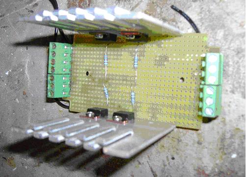
After salvaging, I tried an easier way of laying down copper tracks:
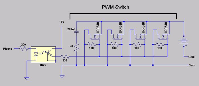
This is the Source side of the switch. Drain is in the back. I got a new CAD program, and I'm still trying to learn how to use it. Anyway, here's my attempt at a circuit:
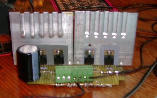
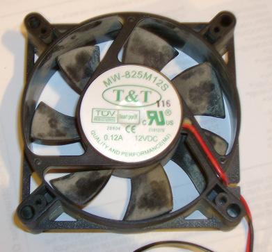
It's getting cold in Canada. Instead of freezing my buns off testing the switch outside, I tested with this victim:
The victim's power Source:
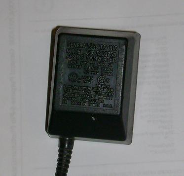
Some details:
Source open voltage 10.10 VDC
Load Voltage 8.19 VDC
Wiring:
Source (+) connected to Fan (+)
Source (-) connected to PWM switch Source
Fan (-) connected to PWM switch Drain
Adding PWM on a DC circuit can induce nasty dips and spikes. When the gate opens and electrons flow, volts can dip. When the gate closes and electron flow stops, volts can spike. That's why I added a cap in version 2. Since the PWM switch is going between rectifiers and batteries, the section of wire between rectifier and PWM switch has the potential to develop high voltage spikes. Not good for rectifiers or MOSFETs.
The standard solution is to add a capacitor. One leg of the cap should connect to the Source side of the switch. The other leg of the cap can go to absolute ground or some point on the (+) volt side. I'm looking at a third option, to put the other leg of the cap on the Drain side of the switch. The PWM signal should leak across the caps, but this can also reduce nasty dips and spikes.
I measured DC volts between PWM switch Source and Drain to get an idea of performance. Here's a graft of volts vs. Duty at 5 kHz:
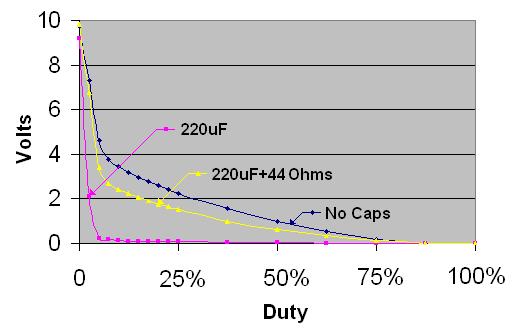
The No Caps line is Volts across the switch vs. duty with no capacitor between Source and Drain. When I added a 220uF cap across the switch, the 220uf line, a lot of the PWM signal leaked across the cap. The 220uF + 44 Ohms line is Volts from Source to Drain with a 220uF cap in series with a 44 Ohm resistor. I tried different cap values but there was no significant change in performance. The resistor value seems important. At about 200 Ohms or higher, Volts vs. Duty follows the No Cap line.
My next crazy idea is to add a Buck Converter after the PWM switch to regulate the messy voltage going into batteries.
Mau
