I have an interesting discovery to share, for those who like software.
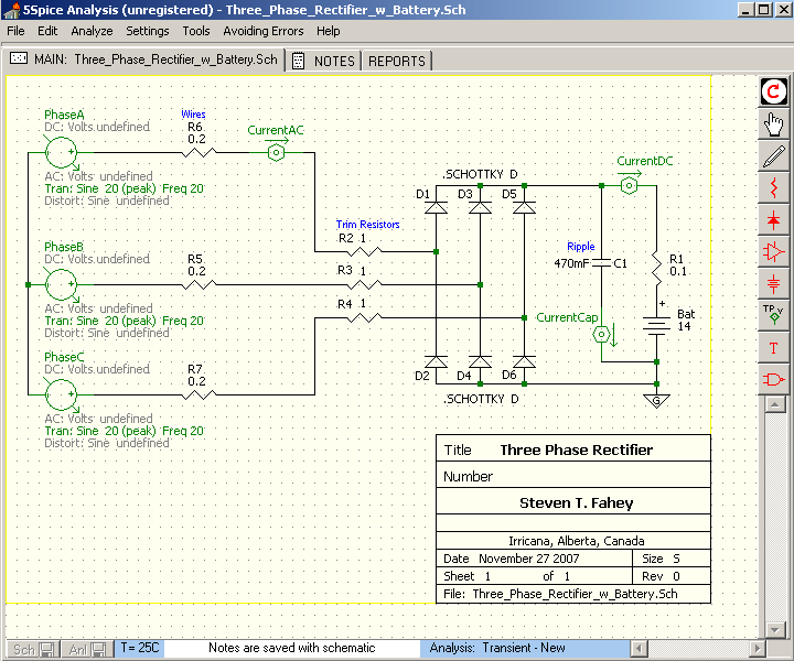
When I heard about Spice, I thought it was just for electronics. I just tried the software out, and it turns out that I can create models of the generator-rectifer-battery system without too much difficulty.
With Spice, I first created three sources of voltage, and that was tricky to set up at first, until I understood what the program was doing. In the schematics I've posted below, I have the generator shown as three 20V (peak) voltage sources, with a 20Hz frequency and they are 120 degrees out of phase with each other. (You have to figure out the time lag, not the phase angle, to get the phases to work).

Next I layed out the set of six identical rectifiers. I picked "Schottky" diodes, but any type will work, and I think the generic bridge you can buy at the hobby store is just silicon. Changing the diode type seems to make no difference in the results.
The battery had me confused for a while until I added a resistance in series. Now I've come to understand that the resistance in the model is the resistance inside the battery. This also changes with the battery's state of charge, so it's a tricky quantity to get a hold of. I just found a value by trial and error that works for the sake of this example.
Later, after getting the basics to work, I started adding things like the "trimming" resistors and Wire resistance. These are resistance values in my own system. The trim resistors are necessary on my setup or the blades of my windmill would stall in light winds.
For fun, I later added a little filter capacitor across the battery. I've heard that you can take out "ripple" in the charging current, and here's a way to see that, and play around with it.
In several places on the schematic you can see the green Current sensors. When the schematic is complete, these icons control the way Spice solves its formulas. The current solutions are shown in graphs on a separate page.

Now that I have some results, I can see several things going on:
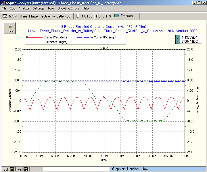
The charging current is about 8 Amps. That's not too different from what you would get if you calculated it by hand:
20V / 1.73 = 11.5V rms
(11.5V - 0.7V) / (0.2ohm + 1ohm + 0.1 ohm) = 8.3 A
There is a spiky current going through the capacitor. It's taking the ripple instead of the battery. If this is a good thing, then this software can help you size up the capacitor.
The AC waveform is a chopped sine (just like Flux says it does). The AC has a ripple at 12x the phase frequency. I thought there would only be 6. The 470 mF capacitor is soaking up almost all of the ripple, about 0.2 Ampere AC with a frequency of 240 Hz.
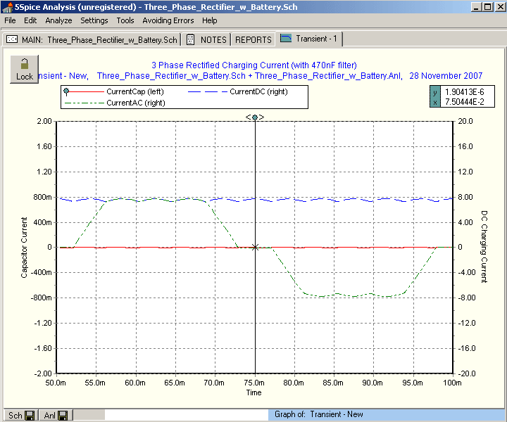
Later, I changed the value of the capacitor from 470 milliF to 470 nanoF, and saw the result is that much less ripple is soaked up by the capacitor.

Although I can't say yet what's good or bad, this is an example of how you can use the simulation to experiment with values of the components and see the result.
Some other things to point out:
The graph puts time on the lower axis. I picked 50 msec to 100 msec to represent one complete cycle (at 20Hz).
The first cycle is a little imbalanced. Maybe there's something I can learn in that, but for now I ignore it to see the more stable second cycle.
If you're interested enough to try Spice for yourself - warning: start simple! I tried laying out the whole shebang at once and I just wasn't getting anywhere. I eventually went right back to basics: 1 DC battery, 1 resistor, and 2 wires, just so that I could learn to "talk" Spice's language. Then worked up, slowly, from there.
The analysis to use for the generator system is the Spice "Transient" analysis. The Spice "AC" analysis doesn't seem to do anything, and obviously a "DC" analysis isn't appropriate to this system. With this in mind, you must set up the generator's voltage sources under the Transient tab, not the AC tab. (Took me 2 hours to figure that out)
Well I can go on and on (I already have) but I'm posting this really to share this neat tool.
For those still reading... http://www.5spice.com
Steven