Author Topic: Microcontrolled LTC3703  (Read 5762 times)

0 Members and 2 Guests are viewing this topic.

bigkahoonaa

  • Jr. Member
  • **
  • Posts: 57
Microcontrolled LTC3703
« on: January 12, 2008, 05:43:21 AM »
OK, so here is my first attempt at a circuit merging a microcontroller with an LTC3703  


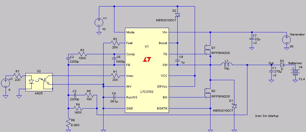
I represented the microcontroller's output pin as the voltage source on the far left (uC).  Software can control whether the output pin is low (0V) or high (5V).  The signal goes through a 4N25 optoisolator and controls Imax, the current limiting pin on U1.  V1 is the LTC3703 and MOSFET driver source.  I set the generator voltage (far right) to 90 volts, and the Batteries to 13.4 volts.  I added diode D3 next to the battery because without it the only voltage seen coming from the converter is battery voltage.  Resistors R4 and R6 set the converter output voltage, and at R4 = 140K and R6 = 8.06K the converter output is about 14.7V, or about 13.8V post diode D3.


I used SwCADIII (http://www.linear.com/designtools/software/switchercad.jsp) from Linear Technology to simulate the circuit buck1.  First, I set the microcontroller output pin high (5V) and calculated:


V[batteries] = volts at the battery

V[out] = volts just before D3

I[V4] = current going into the batteries


I'm amazed at how well the simulation worked, and no, I'm not a Linear Corp Rep.  I expected the converter output voltage to be clamped by batteries, and it was.  With R1 at 20K, the average current going into batteries was about 15 Amps (range 10 to 20 Amps).  


Next, I simulated what would happen with the microcontroller output pin set to low (0V).  This leaves the LTC3703 with no control on current output.  


There's an amazing 380 Amps going into batteries (i.e. > 5000 watts, like that's gona happen).  It's more that likely the generator will stall with such a high load, which should bring everything down.  But, the simulation shows that the LTC3703 can be switched from current control to no control from a single microcontroler pin.


I'm trying to change the circuit so that I can add PWM to regulate the IMAX pin.  I think that adding smoothing capacitors on Imax can do it, but I still need to check components and circuit.

« Last Edit: January 12, 2008, 05:43:21 AM by (unknown) »

domwild

  • Sr. Member
  • ****
  • Posts: 357
Re: Microcontrolled LTC3703
« Reply #1 on: January 11, 2008, 11:20:42 PM »
Very interesting circuit! Thanks.


Have often wondered why our experts do not use those ready-made buck or buck/boost circuits available from companies, such as Linear Technology, etc. for our windmill projects. As I do not have a black belt in electrickery I suggested building such a circuit to Silicon Chip, an Oz magazine.


What I cannot explain, though, is the fact, that if one enters the following data into the LT calculator:


Vin ranging from 36 to 100V

Vout to be for a 36V battery, probably 41VDC (I have a 36V UPS!!)

Amps required to be 10A (hope the mill makes 400W)


the calculator tells me there is no such LT buck chip available, despite the fact that the LTC3703 handles up to 100V and I believe, in my ignorance, that the Amps are just a function of choosing the right FETs.


Where am I wrong?


Regards,


« Last Edit: January 11, 2008, 11:20:42 PM by domwild »

commanda

  • Hero Member
  • *****
  • Posts: 731
Re: Microcontrolled LTC3703
« Reply #2 on: January 12, 2008, 12:32:56 AM »
If you integrate a pwm output from the micro, to give a dc control voltage, and use this to modulate the output voltage (or the output current) of your LTC converter, with a small series resistance (if controlling voltage) feeding the battery, you've just about got your mppt.


Amanda


Footnote to Domwild;


Many of these exotic wonderchips are released with a very particular target niche market in mind. Many of them end up as here today, gone by 3:30pm, never mind tomorrow.

You may or may not have noticed, but everything I have built so far and published here on FL uses generic, or easily substitutable parts. If an LTCxxxx is still available in 20 years from now, and from multiple sources, I may consider using it. Just my personal philosophy on building things I expect to be maintainable long after I've left this mortal coil.

« Last Edit: January 12, 2008, 12:32:56 AM by commanda »

bigkahoonaa

  • Jr. Member
  • **
  • Posts: 57
Re: Microcontrolled LTC3703
« Reply #3 on: January 12, 2008, 07:43:56 AM »
Dom:


I don't have a black belt in electrickery either.  Nice thing about the LTC3703 is that control circuits seem to be independent.  Bad thing is it's SSOP.  I've mounted one on a schmartboard in about 5 minutes, but it's not tested yet.  Don't know why the LT calculator can't find a chip.


Mau

« Last Edit: January 12, 2008, 07:43:56 AM by bigkahoonaa »

thirteen

  • Hero Member
  • *****
  • Posts: 980
  • Country: us
  • Single going totally off grid 1,1, 2013
Re: Microcontrolled LTC3703
« Reply #4 on: January 12, 2008, 09:23:00 AM »
Will your microcontroler have a heating problem trying to push the larger amperage towards the batteries, I am thinking of surge demands from the battery inverters or a direct shorting of a battery. And would this handle a heavey back surge from the batteries (short or wrong hookup).  Surging or low power from the genset. Just thinking it's been eons since I looked at a controling circuit system.
« Last Edit: January 12, 2008, 09:23:00 AM by thirteen »
MntMnROY 13

tecker

  • SuperHero Member
  • ******
  • Posts: 2183
Re: Microcontrolled LTC3703
« Reply #5 on: January 12, 2008, 09:36:08 AM »
No way that hexfet will handle the amperage I have trouble with the manufacture's rateing 94 a at 10 volts . I know this is a simulation and the fet would have to be stacked.
« Last Edit: January 12, 2008, 09:36:08 AM by tecker »

tecker

  • SuperHero Member
  • ******
  • Posts: 2183
Re: Microcontrolled LTC3703
« Reply #6 on: January 12, 2008, 10:41:31 AM »
This is a good circuit to talk control techniques the shunt to ground could easily be set to a bond between battery banks . The getset and voltage reference set to total the two banks.With bank a set to charge bank b could could easily be a ground reference . Add in the load of your user circuit powered by bank b( A B switching in place)And the need for a shunt may for the most part eliminated unless you need the heat. Another thing that I have noticed with switching semiconductors is they run cooler switching on the neg side of a load .
« Last Edit: January 12, 2008, 10:41:31 AM by tecker »

bigkahoonaa

  • Jr. Member
  • **
  • Posts: 57
Re: Microcontrolled LTC3703
« Reply #7 on: January 12, 2008, 04:55:43 PM »
tecker:


You're right.  The bottom FETs can't take high current.  I didn't optimize components in the circuit.  No point in doing so, unless I can integrate the micro with U1. The simulation is nice.  It can show where nasty spikes can happen, and they will.


Mau

« Last Edit: January 12, 2008, 04:55:43 PM by bigkahoonaa »

domwild

  • Sr. Member
  • ****
  • Posts: 357
Re: Microcontrolled LTC3703
« Reply #8 on: January 12, 2008, 08:54:27 PM »
Amanda,


Your comments are very much appreciated. Your MPPT comment was something I had in my little mind, too. If one can vary voltage (or amps) and gets a target voltage into the battery, one can match the load to the mill output and battery condition.


Re "wonder" chips: There is certainly more personal satisfaction in "rolling your own" rather than relying on a purchased black box.

« Last Edit: January 12, 2008, 08:54:27 PM by domwild »

domwild

  • Sr. Member
  • ****
  • Posts: 357
Re: Microcontrolled LTC3703
« Reply #9 on: January 14, 2008, 01:24:04 AM »
Mau,


Keep the world posted once you add PWM to your Imax pin as this would be a MPPT solution.


How many Amps do you think your circuit can handle with generous heatsinking??


Regards,

« Last Edit: January 14, 2008, 01:24:04 AM by domwild »