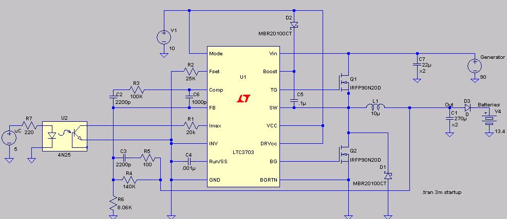
OK, so here is my first attempt at a circuit merging a microcontroller with an LTC3703

I represented the microcontroller's output pin as the voltage source on the far left (uC). Software can control whether the output pin is low (0V) or high (5V). The signal goes through a 4N25 optoisolator and controls Imax, the current limiting pin on U1. V1 is the LTC3703 and MOSFET driver source. I set the generator voltage (far right) to 90 volts, and the Batteries to 13.4 volts. I added diode D3 next to the battery because without it the only voltage seen coming from the converter is battery voltage. Resistors R4 and R6 set the converter output voltage, and at R4 = 140K and R6 = 8.06K the converter output is about 14.7V, or about 13.8V post diode D3.
I used SwCADIII (http://www.linear.com/designtools/software/switchercad.jsp) from Linear Technology to simulate the circuit buck1. First, I set the microcontroller output pin high (5V) and calculated:
V[batteries] = volts at the battery
V[out] = volts just before D3
I[V4] = current going into the batteries

I'm amazed at how well the simulation worked, and no, I'm not a Linear Corp Rep. I expected the converter output voltage to be clamped by batteries, and it was. With R1 at 20K, the average current going into batteries was about 15 Amps (range 10 to 20 Amps).
Next, I simulated what would happen with the microcontroller output pin set to low (0V). This leaves the LTC3703 with no control on current output.

There's an amazing 380 Amps going into batteries (i.e. > 5000 watts, like that's gona happen). It's more that likely the generator will stall with such a high load, which should bring everything down. But, the simulation shows that the LTC3703 can be switched from current control to no control from a single microcontroler pin.
I'm trying to change the circuit so that I can add PWM to regulate the IMAX pin. I think that adding smoothing capacitors on Imax can do it, but I still need to check components and circuit.