Author Topic: Living and learning  (Read 1910 times)

0 Members and 1 Guest are viewing this topic.

Buzz Hacksaw

  • Newbie
  • *
  • Posts: 22
Living and learning
« on: May 22, 2008, 02:59:40 AM »
I have constructed a steel dbl rotor, as I threatened in last my posting. Here are some photos and test results. Can anyone verify these figures? I personally don't think they can be correct. If they are I have created a monster. My intention was to generate heat for my garage next winter. Little did I realize I would need a prop the size of my house, and 50 ft in the air, Bet the neighbours notice LOL.

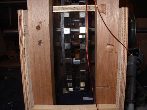
 I've got a few mechanical bugs to work out, wobbling, stator construction, housing, decent bearings, attachment to the shaft and support within the housing. Other than that I'm off to the races.

 I'm learnin' a lot an' hav'in fun.

By the way, the electric motor in one of the photos is fairly new from a dryer. Can anyone help me with a way to hook it up so I can turn my creation instead of using a drill?

Thanks.

Values are projected after 1 coil tested at the stated RPM.


2 of 16" x ¼" iron Rotors, 72 of magnets 1/2" x 1/2" x2" , coils 125 turns of 18 g copper    

RPM                I = E/R    P = E x I   

200                            Ohms    Hz    Volts    Amps    Watts    Avg.P per

                             R        E    I    P   


  1. Coil                             0.5    60    9.3    18.6    172.98    173.0
  2. Coil Series                    1    60    18.6    18.6    345.96    173.0
  3. Coil Series                    1.5    60    28    18.6    518.94    173.0
  4. Coil Series                    3    60    56    18.6    1037.88    173.0
  5. Coil Series                    4.5    60    83.7    18.6    1556.82    173.0
  6. Coil Series                    9    60    167    18.6    3113.64    173.0
  7. parallel of 9 series coils    2.25    60    83.7    37.2    3113.64    173.0
  8. parallel of 6 series coils    1    60    55.8    55.8    3113.64    173.0
  9. parallel of 3 series coils    0.25    60    27.9    111.6    3113.64    173.0
  10. of 16" x ¼" iron Rotors, 72 of magnets 1/2" x 1/2" x2" , coils 125 turns of 18 g copper   


RPM        Increased x    1.29    I = E/R    P = E x I   

260                           Ohms    Hz    Volts    Amps    Watts    Avg.P per

                            R        E    I    P   


  1. Coil                            0.5    78.0    12    24.0    288.00    288.0
  2. Coil Series                   1    78.0    24    24.0    576.00    288.0
  3. Coil Series                   1.5    78.0    36    24.0    864.00    288.0
  4. Coil Series                   3    78.0    72    24.0    1728.00    288.0
  5. Coil Series                   4.5    78.0    108    24.0    2592.00    288.0
  6. Coil Series                   9    78.0    216    24.0    5184.00    288.0
  7. parallel of 9 series coils   2.25    78.0    108    48.0    5184.00    288.0
  8. parallel of 6 series coils   1    78.0    72.0    72.0    5184.00    288.0
  9. parallel of 3 series coils   0.25    78.0    36.0    144.0    5184.00    288.0
  10. of 16" x ¼" iron Rotors, 72 of magnets 1/2" x 1/2" x2" , coils 125 turns of 18 g copper   


RPM        Increased x    1.72    I = E/R    P = E x I   

334                            Ohms    Hz    Volts    Amps    Watts    Avg.P per

                            R        E    I    P   


  1. Coil                             0.5    100.2    16    32.0    512.00    512.0
  2. Coil Series                    1    100.2    32    32.0    1024.00    512.0
  3. Coil Series                    1.5    100.2    48    32.0    1536.00    512.0
  4. Coil Series                    3    100.2    96    32.0    3072.00    512.0
  5. Coil Series                    4.5    100.2    144    32.0    4608.00    512.0
  6. Coil Series                    9    100.2    288    32.0    9216.00    512.0
  7. parallel of 9 series coils    2.25    100.2    144    64.0    9216.00    512.0
  8. parallel of 6 series coils    1    100.2    96.0    96.0    9216.00    512.0
  9. parallel of 3 series coils    0.25    100.2    48.0    192.0    9216.00    512.0


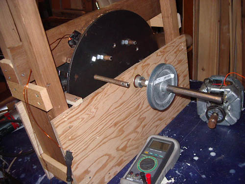
Note the threaded bar sticking out of the rotor. I drilled and taped six holes on one of the rotors to facilitate disassembly. They work like a charm and only 3 are really needed.


I am planning a vertical helix, or mabey horizontal, i dunno. I thinking the full length of the peak of my garage roof would work well to collect wind for horizontal helix. Comments welcome.

« Last Edit: May 22, 2008, 02:59:40 AM by (unknown) »

commanda

  • Hero Member
  • *****
  • Posts: 731
Re: Living and learning
« Reply #1 on: May 22, 2008, 02:44:36 AM »
If that's open circuit volts and short-circuit amps, then your power figures are way off. For maximum power transfer, assuming you can constantly adjust the load for varying rpm, you need to use half the voltage, and possibly half the current, which gives you a figure of one quarter the power vs open circuit volts times short circuit amps.


For an air-cored axial flux machine, the internal impedance is fairly close to the dc resistance. Taking your very first line as an example, and loading it such that the load = the internal dc resistance;


 Coil                             0.5    60    9.3    18.6    172.98    173.0


9.3 volts open circuit into a 0.5 ohm load, 9.3/2 (4.65) volts into half an ohm

power = 43.245 watts (not 172.98).


Amanda

« Last Edit: May 22, 2008, 02:44:36 AM by commanda »

Buzz Hacksaw

  • Newbie
  • *
  • Posts: 22
Re: Living and learning
« Reply #2 on: May 22, 2008, 04:59:28 AM »
Thank you you commenting.

This is calculated amps. Not short circuit. I read that short circuit amp reading is useless information. Just for kicks I tried to take a S.C.reading, as I did on my first genny, and the thumping was extremely powerful.

I think it is good that I've overcalculated. Does this mean I can calculate sweep area on the lower power values?
« Last Edit: May 22, 2008, 04:59:28 AM by Buzz Hacksaw »

Buzz Hacksaw

  • Newbie
  • *
  • Posts: 22
Re: Living and learning
« Reply #3 on: May 22, 2008, 06:36:43 AM »
I have a bunch of 220 v baseboard heaters pulled out of my house after it was converted to gas heat. Can these be used in any way for heat in my garage with this home built genny? 1500w, 1000w and 750w stored up in the trusses in the garage.
« Last Edit: May 22, 2008, 06:36:43 AM by Buzz Hacksaw »

electrondady1

  • SuperHero Member
  • ******
  • Posts: 3122
  • Country: ca
Re: Living and learning
« Reply #4 on: May 22, 2008, 07:45:11 AM »
hey,

 good to see your progress.

the number one thing do do next is get rid of that wobble.

once your machine runs true you have something to build on.

don't throw your base board heaters out.
« Last Edit: May 22, 2008, 07:45:11 AM by electrondady1 »

Buzz Hacksaw

  • Newbie
  • *
  • Posts: 22
Re: Living and learning
« Reply #5 on: May 22, 2008, 08:05:35 AM »
The wobble is less than 1/16 " x 2. I have looked for on off the shelf coupling or whatever for the 3/4" shaft. No luck so far. Any suggestions?
« Last Edit: May 22, 2008, 08:05:35 AM by Buzz Hacksaw »

Buzz Hacksaw

  • Newbie
  • *
  • Posts: 22
Re: Living and learning
« Reply #6 on: May 22, 2008, 08:08:22 AM »
I put a load, 171.1 Ohms, and tested voltage. I didn't notice any difference in voltage. How can I test as you suggest?
« Last Edit: May 22, 2008, 08:08:22 AM by Buzz Hacksaw »

TomW

  • Super Hero Member Plus
  • *******
  • Posts: 5130
  • Country: us
Re: Living and learning
« Reply #7 on: May 22, 2008, 08:13:52 AM »
Buzz;


As far as those heaters are concerned, they likely need 220 volts to get the wattage they rate them at.


Otherwise, like on 12, 24 or 48 volts they will be seriously derated on power they can pull.


It is entirely feasible to wind a turbine stator for these voltages. Check out Dave B and his heating turbine diaries for some ideas how he does it.


The options are nearly endless on how you can use this power. They are not always obvious, however.


Good luck with it.


Tom

« Last Edit: May 22, 2008, 08:13:52 AM by TomW »

finnsawyer

  • Hero Member
  • *****
  • Posts: 1565
Re: Living and learning
« Reply #8 on: May 22, 2008, 09:10:46 AM »
The ratio of your open circuit voltage to your short circuit current should equal the resistance of the alternator.  I checked one set of your numbers, the 18 coils in series from the first listing and got 8.9 ohms, so your resistance measurement of 9 ohms appears to be correct.  You can use a Thevenin Equivalent model of a voltage source equal to the open circuit voltage in series with a nine ohm resistor to predict the current and power into any load for a given RPM.  For instance, if you connect a 9 ohm load across the alternator's output, half the open circuit voltage will appear across the load resistance.  You can calculate the power the load would need to dissipate from that.  I happen to have a 9 ohm 113 watt resistor in my possession, but even that might have too low a power rating.  Be careful.


I think you can see from this little discussion the importance of doing some study of basic circuit theory.  

« Last Edit: May 22, 2008, 09:10:46 AM by finnsawyer »

electrondady1

  • SuperHero Member
  • ******
  • Posts: 3122
  • Country: ca
Re: Living and learning
« Reply #9 on: May 22, 2008, 10:35:44 AM »


can't tell from your photo what your using now but

you will need something hefty to tie the rotors to the shaft .

some sort of mandrel(s) with set screws

maybe even a steel pully.

as long as it has a face that is a true 90 deg. to the shaft

 or a central spacer with two parallel faces .

now might be the time to get to know your local machinist. lol
« Last Edit: May 22, 2008, 10:35:44 AM by electrondady1 »

Buzz Hacksaw

  • Newbie
  • *
  • Posts: 22
Re: Living and learning
« Reply #10 on: May 22, 2008, 11:42:55 AM »
Thank you for your comment. Esp "Be Careful". My next door neighbour is an electrician and he tells me now is the time to "Pay attention". Just the force of momentum is enough to seriously injure.

« Last Edit: May 22, 2008, 11:42:55 AM by Buzz Hacksaw »

Buzz Hacksaw

  • Newbie
  • *
  • Posts: 22
Re: Living and learning
« Reply #11 on: May 24, 2008, 06:06:09 AM »
 I built a stator last night out of MDF, to hold all of the coils, and assembled it. Now the coupling of the shaft to the rotor has become a real issue. There is a lot of resistance in the rotor now and the shaft spins. I can only get the rotor to turn slowly. This even when no coils are connected to anything. I am working on a coupling today. Is this resistance due to the magnet/copper proximity? ie. the phenomenon of dropping a magnet down a copper pipe.
« Last Edit: May 24, 2008, 06:06:09 AM by Buzz Hacksaw »

Buzz Hacksaw

  • Newbie
  • *
  • Posts: 22
Re: Living and learning
« Reply #12 on: May 25, 2008, 08:54:25 AM »
The coupling of the shaft to rotor is now complete. Tests have been done on open circuits and results are precisely as forecast. I can get a desk fan operating no problem. The 750 watt baseboard heater is another issue. The resistance on the machine is huge. I'm trying to push a 750 watt heater with a 450 watt drill. I'm starting to understand the concept of cut in and air gap. Currently I have a gap of .7 to .75 in. and the coils are just over .56 +/- in. thick. I need find a way to disconnect the load from the gen. until the voltage/rpm gets high enough or the darn thing will never get moving. Next I have to figure what size of wind catcher at what wind velocity will be needed to achieve this.

 I have designed a double helix in auto cad. Now my little brain is feverishly working at ways I might actually make it.


« Last Edit: May 25, 2008, 08:54:25 AM by Buzz Hacksaw »