Hi Ungrounded - I should do some tests. What's 'ideal' here really depends on how the magnets are spaced apart. That's at least as important as the size of the magnet itself. There are times when its benificial to build a smaller machine - and crowd the magnets and I would argue that in those cases it's benificial to wind the inside of the coil small. I did lots of tests like this a couple years ago but the magnet rotors I used are different that what I normally do.
One recent test is interesting though if you recall a couple of mondays ago when we were playing with Richs machine, which has 12 2" diameter magnets around the magnet rotor. We used the same coil winder (same shape coils) that I normally use for 1" x 2" magnets (and the hole is ever so slightly smaller than 1" x 2" - its 1" at the top, 2" long, and 3/4" on the bottom to give a slight wedge shape). In that arrangement, if I made the holes in teh coils the size of the 2" disks I'd have about 1/2" of space for the coil legs which I don't believe would allow for enough wire - and... we'd have about half the wire in teh coil 'wasted' (parallel to, not perpendicular)on top and below the path of the magnets.
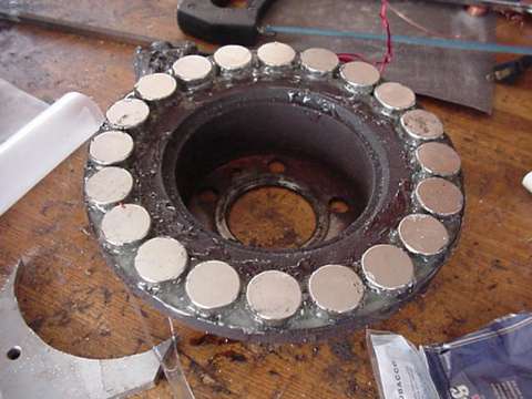
In that test we tried the same stator with two rotors (one rotor had 1" x 2" blocks and the coils were 'close' to what most folks would consider proper if not a bit wide in the legs). We measured DC Volts (after the rectifiers) and rpm.
With the 1" x 2" magnets we got 12VDC @ 284 rpm.
with the 2" dia round magnets we got 12VDC @ 196 rpm.
We used the same coils so resistance is the same in both tests. The 2" dia magnets are about 50% bigger in surface area and they got us nearly 50% lower cutin speed even though the coils were much too small in the middle. Obviously - the windings that were 'smaller' than the magnet were doing us lots of good here.
I expect I could've gone to somewhat larger rotors, used the same magnets - wound perfect 'textbook' coils and perhaps gained a bit more power at the cost of more copper/resin/ and steel.
This is the most relevant test I've done recently on this issue - I'll do more of this stuff soon.
Ill comment on some of your text now...
"Reducing the size of the hole by winding more coil there increases the amount of time the magnet is moving onto a coil side. This leaves the slope of the edges of the trapezoid the same but lengthens them."
Yes... for a higher peak voltage I expect.
"The trapezoids becomes taller, narrower at the top (bottom in the inverted case), and wider at the base. Voltage goes up, but resistance goes up too. (The current delivered to the batteries goes up because the batteries are charged at a non-zero voltage.)"
Yes - that makes sense.
"But once you've wound the hole down to the width of the magnet - so the two trapezoids touch - the situation changes. Now adding more wire gives you no added power, because the magnet impinges on the far side of the coil and starts canceling out the voltage induced in the near side. Your extra turns beyond this point produce NO additional power. "
Nice explanation... it makes perfect sense but it doesn't seem to actually work out that way for me.
"(While the trapezoids continue to rise they also narrow in proportion, becoming triangles when the width of a coil side is the width of the magnet and the hole is filled.) But it DOES produce added resistance, reducing your charging current for a given voltage, and increasing your heating for a given current."
Yes - I could see that if what you say is true here. I don't think it actually works out that way though. It makes me think of old single phase machines I made a few years ago like this (kind of an extreme case):
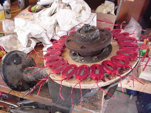
In that case.. there's no way that I could've made the hole the size of the magnet and it actually worked pretty well considering. I did lots of testing for coil shape on that one.
"So any wire wound within the footprint of the magnet when it's centered on the coil is not just wasted copper, but actually hurts your output."
I think it hurst output like you said - when the magnet is centered on the coil. At other times though it can be benificial. I think the ideal hole in the coil, and overall coil size is a compromise between teh size/shape of the magnet - and the spacing of the magnets. My 17' machine is another case where magnets are crowded pretty close, the coil holes need to be smaller than the magnets in order to have any room for wire. In that case the holes look more like the gaps between the magnets than they look like the magnets themselves. Peak voltage happens when an opposite pole is over each leg of a coil so to me it makes sense to keep the space between the poles in mind.
"The effect of field spreading is to widen the pole and make its edges "fuzzy". This bends the trapezoids' sides into S curves, so the waveform more closely approximates a sine wave. It also means your hole should actually be very slightly wider than the magnet for optimum performance. "
If I had to make them slightly bigger... there'd be no room at all for copper in lots of my machines! ;~)
(But with opposing pole pieces and a small gap this effect isn't pronounced enough to make it worth trying to compensate for it. Just make the hole the size of the magnet and you won't be wasting very much copper and power.)
I'm very much a trial and error sort of person I guess... I'll do some more tests on this though - it'd be fun. What I've done so far though seems to suggest that windings smaller than the magnet can contribute.
