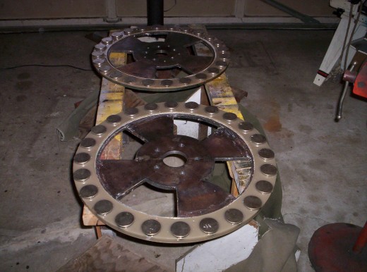
I was surprised to see how the 48 volt cut in was at 48 RPM rectified, but I think Im happy with that. The air space is now 15/16" wide. Rotors are 24 & 3/4" dia, 24 2" by 1/2" rnd mags N38 each rotor and 18 coils two in hand #15 wire with 75 turns. First picture, is of the yaw bearings, I wanted something that would turn very easy in very light winds, and this did the trick. you can see the top bearing, and there is enother one like it at the bottom of the 16" section of 4" pipe.
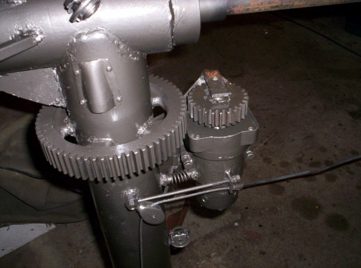
This is a low RPM, high torque 12 volt motor that will have a cable running down the outside of the tower along with the power cable for the motor. The cable will engage the gears and will turn the turbine out of high wind, and lock it in place, or at least give me a chance to short out the geny at a low RPM. Im doing this because I will have no furl. I live in a low wind area, and am counting on the turbine going into stall before it runs wild. I guess we will see!
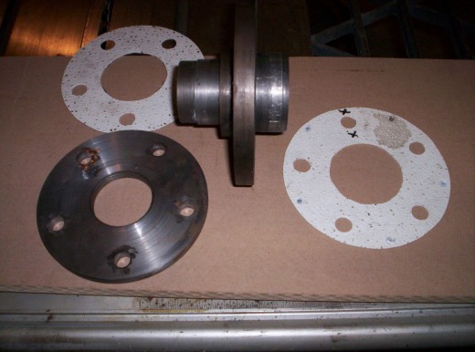
This shows a small sleeve that will alow the back end of the hub to slide inside to help keep water out of the rear bearing.
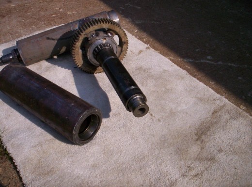
This is a hub from a 1996 ford two wheel drive that has had the rotor machined off, leaving the flange, and also machined to accept the two rotors at close tollerance. also in the picture is the outer flange and shims used to set air gap.
Rotors poured with vinyl ester with sheetrock texture added.
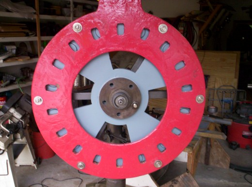
30" stator with back rotor on. one can see how the mags line up in phase, and out of phase.
This shows the front flange in place, and ready for the front rotor.
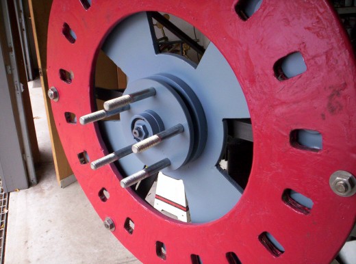
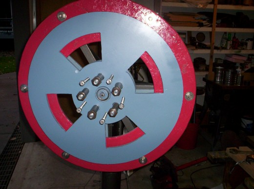
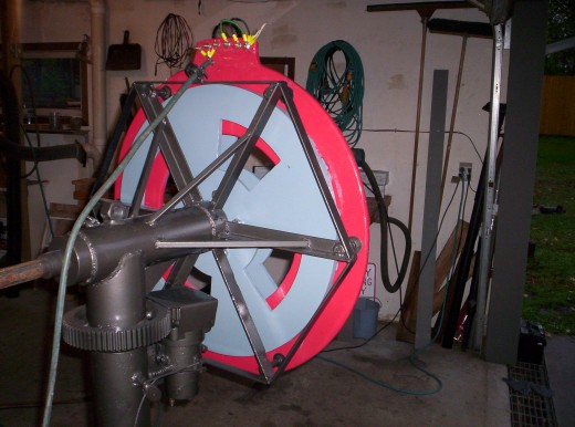
Front rotor in place, with 5/8" by 7" thru bolts in place, along with the jack screws.
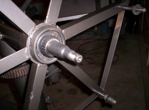
view of back side, showing stator supports. I was able to use 3 & 1/2 by 5/8" stainless steel bolts to mount stator, I welded the heads to the bracket, and have enough threads to set stator.
Now to find cedar for the blades, lots of fun.
