What ever happened to bioelectrifyer web site?? Any one know?? I disappeared a couple of months ago, never to be heard from again??
In any case, some people have been asking me if I had the circuit, long before the web site disappeared, I copied it.. so if i break any rules here or infringe, I apologize. The information at the time was totally free from the web site, but since it not longer exists I don't think they will mind me doing this.. Here is the web site on the charge controller before it went to digital death... All credits are included. There was no copywrite information anywhere on the web site. By the looks of it, he was giving away the information to help others. (see the bottom of this post)...
-----------------------------------------------------------------------------------
Welcome to the
CIRCUITS MAXIMUS web site!
Gadgets and Gizmo's by
Thomas M. Miller
Amateur Radio WA8YKN
216 East 10th Street
Ashland, Ohio 44805
----------------------------------------------------------------------------------
BUILD A SIMPLE
CHARGE CONTROLLER
FOR WIND AND SOLAR POWER SYSTEMS
Once our wind generators and solar panels were up and running, the next obvious requirement was some sort of charge controller, since continuous overcharging would boil the electrolyte dry and ruin the expensive battery bank. Several small controllers came bundled with the solar panels, but they were totally unsuitable for wind power use.
Charge controllers intended for solar panels work by monitoring the battery voltage, and once it reaches full charge, the controller simply shorts the solar panel leads together. This doesn't harm the solar panels, but it does waste whatever power they're generating. The energy ends up heating the transistors in the controller.
This type of controller is not ideal for a wind generator, since shorting the output of the genny while it's spinning at high speed will generate a huge current spike, possibly destroying the controller and perhaps even the generator in the process. On the other hand, simply unhooking the generator from the batteries is not a good idea either, since with no load on it, the generator might overspeed in a strong wind and destroy itself.
The ideal solution is to charge the batteries until they reach a full charge, then switch to an alternate load where the energy can be safely handled. While we're at it, this energy should be used for some useful purpose, such as supplementing a water heater or powering a peltier-junction refrigerator, but in a pinch, a bank of 12 volt light bulbs will do.
The above schematic shows the simple charge controller circuit. The incoming battery voltage is divided in half by a pair of 3.3K resistors, so the trip points are adjusted to one-half the desired levels. The actual trip points will depend on your particular batteries, but a good starting point is 14.5 volts for full-charge, and 11.8 volts for discharged. In this case, the trimpots should be adjusted to read 7.25 volts at TP-A and 5.9 volts at TP-B. You will probably need to monitor your battery voltage through several charge - discharge cycles to determine the perfect trip points for your system.
The outputs of the controller are latched, and drive a pair of IFR510 power FETs, which serve as relay drivers. If you use a double-throw relay, only one output is necessary, since the relay can switch the incoming power to either the batteries or the alternate load as required. The second output can be used to switch a small 12 volt DC muffin fan to vent hydrogen gas from the battery enclosure to prevent the danger of explosion when charging the batteries.
The two push-buttons provide a way to toggle the output manually when the battery voltage was in the "null zone" between the trip points. By momentarily pressing one of the buttons, the output state will reverse and latch. A 1K resistor prevents a dead short, just in case someone decides to press both buttons at once!
--------------------------------------------------------------------------------
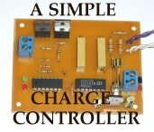
The charge controller is built on a small printed circuit board, as shown below. The diagram above shows the component layout. Be sure to install the I.C.s and capacitors correctly, as reversing them will most likely generate a puff of smoke. Terminal blocks are soldered to the board for the incoming 12 volts and for connections to the relay coil.
--------------------------------------------------------------------------------
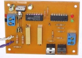
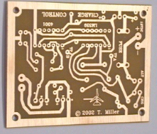
...(LEFT) COMPONENTS INSTALLED .... ....(RIGHT) BARE CIRCUIT BOARD...
--------------------------------------------------------------------------------
Since the incoming power is produced by several different types of surplus solar panels and homebuilt wind generators each producing different voltages, they can't just all be hooked together... each has it's own blocking diode in series with the positive lead. When the battery is charging, each source is pulled down to the battery terminal voltage, so each source contributes whatever current it's capable of producing. Each blocking diode has to be sized for the current that source can generate. The negative lead from each source is connected to ground.
Here's the hookup as it's working here. As long as the batteries are charging I can see the red LED glowing. As soon as the trip voltage is reached, the red LED goes out and the green one comes on, and the power is shunted to the alternate load. This way, no power is wasted.
--------------------------------------------------------------------------------
--------------------------------------------------------------------------------
FRONT PAGE....
SO WHAT'S THIS WEBSITE?
I'm an engineer by trade, and I also enjoy designing interesting electronic gadgets and gizmos in my spare time. Since I also enjoy writing, I usually combine the two and end up writing articles about interesting electronic gadgets and gizmos. I also like to encourage other people to experiment and build these projects.
Generally, I will design a printed circuit board for all my electronic projects (published either in a magazine or on the web) and I always make that board available for a small fee so that others can duplicate the circuit. I can also offer a few of my designs fully assembled for those who are "soldering iron challenged" but still want to get in on the fun.
Another thing I do is to inject an occasional "editorial." These can range from advice on emergency preparedness to shedding some light on something going on behind our backs, or even a report on a book I find particularly interesting. Hey, it's my web site, and my soapbox, so take it for what it's worth.
In the near future, I intend to work up kits for some of my designs. I'm building a small CNC drilling machine to help in the fabrication of circuit boards. The time-consuming part is writing a good set of instructions. Hopefully, I'll get time to put this project in motion very soon.
----------------------------------------------------------------------------------
