Author Topic: Wiring Schematic  (Read 1460 times)

0 Members and 1 Guest are viewing this topic.

lglagasse

  • Newbie
  • *
  • Posts: 17
Wiring Schematic
« on: March 25, 2008, 11:55:52 PM »
Hi Guys:


Forgive me, I know this must be a duplicate posting. I spent hours checking to find old postings.


A while back someone posted a good schematic diagram of a complete wind system but when I printed I was missing part of the diagram.


I have a 17 ft., 48 volt, dual rotor project as the old style from otherpower ongoing.


I am in need of a diagram showing dump load [I'll probably heat water] and inverter and controller hook up. I have stop switch, rectifiers, and fuses worked out, from there forward is whatI need.


Thanks in advance for the help.


lglagasse

« Last Edit: March 25, 2008, 11:55:52 PM by (unknown) »

wooferhound

  • SuperHero Member
  • ******
  • Posts: 2288
  • Country: us
  • Huntsville Alabama U.S.A.
    • Woofer Hound Sound & Lighting Rentals
Re: Wiring Schematic
« Reply #1 on: March 26, 2008, 12:56:44 AM »
« Last Edit: March 26, 2008, 12:56:44 AM by (unknown) »

SparWeb

  • Global Moderator
  • Super Hero Member Plus
  • *****
  • Posts: 5452
  • Country: ca
    • Wind Turbine Project Field Notes
Re: Wiring Schematic
« Reply #2 on: March 26, 2008, 01:03:39 PM »
Here's a schematic of my complete system, if it helps:


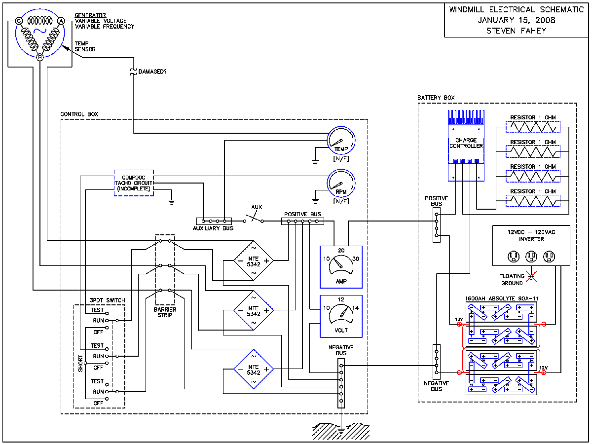
Click on the small image to see the full-size.  Then you can use the right mouse button so "save as" to your computer's hard drive.  When you print, see if the software you use allows the image to be resized, to fit the paper.


Since January, when I drew this, I have removed the povisions for the tacho circuit.  I will instead be adding output terminals to transmit data to a computer.  I do not have fuses protecting the inverter, which I admit is not correct.


If you go through my old postings, and diaries, you can see the progression of adding dump loads, what I used, etc.

« Last Edit: March 26, 2008, 01:03:39 PM by (unknown) »
No one believes the theory except the one who developed it. Everyone believes the experiment except the one who ran it.
System spec: 135w BP multicrystalline panels, Xantrex C40, DIY 10ft (3m) diameter wind turbine, Tri-Star TS60, 800AH x 24V AGM Battery, Xantrex SW4024
www.sparweb.ca

lglagasse

  • Newbie
  • *
  • Posts: 17
Re: Wiring Schematic
« Reply #3 on: March 26, 2008, 01:25:16 PM »
Thanks Steve:


Your schematic is the one I was looking for. I did not see this in your diary though.


I am setting my system in this same manner.


regards


lglagasse

« Last Edit: March 26, 2008, 01:25:16 PM by (unknown) »

lglagasse

  • Newbie
  • *
  • Posts: 17
Re: Wiring Schematic
« Reply #4 on: March 26, 2008, 01:29:12 PM »
Steve, are the dump load resisters 1 ohm each? My printer cuts off the right side of the page.


Thanks


lglagasse

« Last Edit: March 26, 2008, 01:29:12 PM by (unknown) »

Sly

  • Newbie
  • *
  • Posts: 44
Re: Wiring Schematic
« Reply #5 on: March 26, 2008, 06:23:58 PM »
Hi lglagasse,


I can view Steve's schematic on my PC and yes they are 1 ohm each and there are 4 of them configured in parallel.


Sly

« Last Edit: March 26, 2008, 06:23:58 PM by (unknown) »

SparWeb

  • Global Moderator
  • Super Hero Member Plus
  • *****
  • Posts: 5452
  • Country: ca
    • Wind Turbine Project Field Notes
Re: Wiring Schematic
« Reply #6 on: March 29, 2008, 08:09:33 PM »
Hi lglagasse,

Hey that's some funny kind of software you're using that refuses to re-size the image for you.

I have very flexible software here - I can make a new file any way you want.

What format, size and resolution do you want?  Send me an e-mail.


I must apologize for a bit of confusion on the diagram: those resistors are printed 1 ohm, but I actually have 2 Ohm resistors installed, in parallel.  The bank's resistance is therefore 0.5 Ohms.  When the batteries are up to 14V and the charge controller is dumping power, then the bank of resistors will pass 28 Amps.  Each resistor will be dissipating 7 Amps, hence about 100 Watts.  Each resistor is rated for 300 Watts.


I should fix that number on the resistors to prevent any further confusion, I guess.

« Last Edit: March 29, 2008, 08:09:33 PM by (unknown) »
No one believes the theory except the one who developed it. Everyone believes the experiment except the one who ran it.
System spec: 135w BP multicrystalline panels, Xantrex C40, DIY 10ft (3m) diameter wind turbine, Tri-Star TS60, 800AH x 24V AGM Battery, Xantrex SW4024
www.sparweb.ca