Author Topic: Washing Machine Induction Motor Conversion.  (Read 24210 times)

0 Members and 1 Guest are viewing this topic.

sPuDd

  • Jr. Member
  • **
  • Posts: 51
Washing Machine Induction Motor Conversion.
« on: December 31, 2006, 04:05:32 AM »
My 12 year old washing machine finally fell apart, and I

splashed out on a new one. While stripping the old one

for useful bits, I caught sight of the old motor.
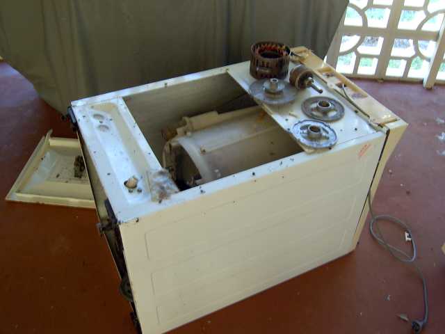


A quick check showed it was an induction motor. I'm in

Australia, so our stuff is 240VAC 50Hz. Although it had

no spec plate or even a model number, I estimate it was

about a 1/2hp to 1hp (~375W to 750W)? Seems to have a

4-pole 2-phase type of arrangement. It had a capacitor for

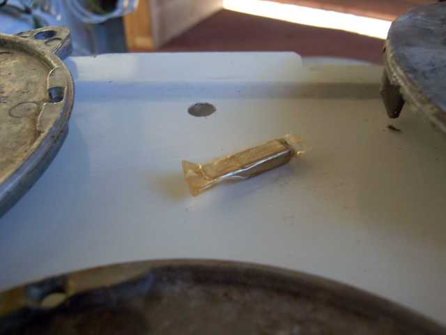
start/run on the second phase and a thermal fuse imbedded

in the windings. I bypassed the fuse to stop it doing anything

silly. This is a close up of the fuse.


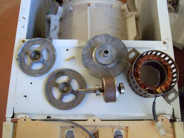
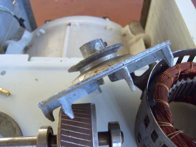
The belt pulley was made of aluminium, and I will turn that

down in the lathe to become part of the blade hub later.


The rotor was about 80mm in diameter, and about 30mm

deep. I thought about buying some long narrow bar magnets

and skewing them slightly. But I remembered I had a pack

of 100 13mm x 5mm disk magnets. Although they are small

and fiddly, I got them for about AU$15 and stacking them

should improve the flux output.
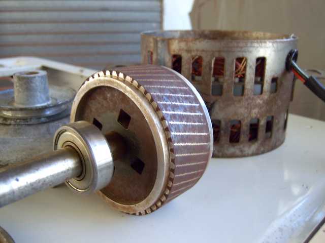


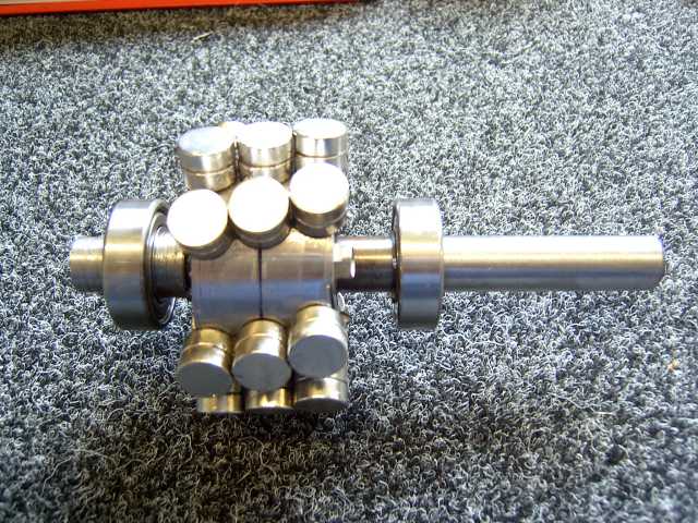
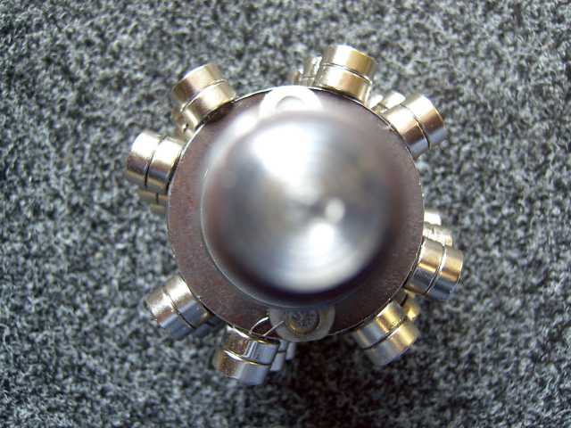
This is what the rotor looked like after being machined down

and with the magnets stacked in a 3x2 configuration. I seem

to allow more space between poles than a lot of other conversion

people do, perhaps I'm fussy about cancellation in the waveform.

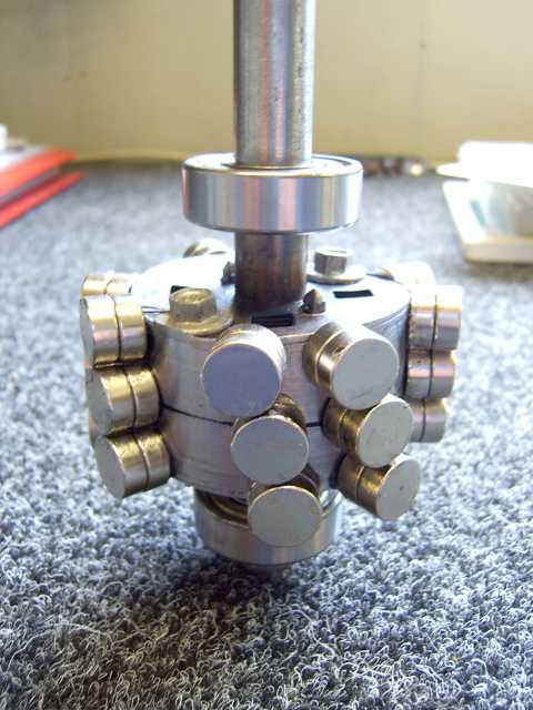
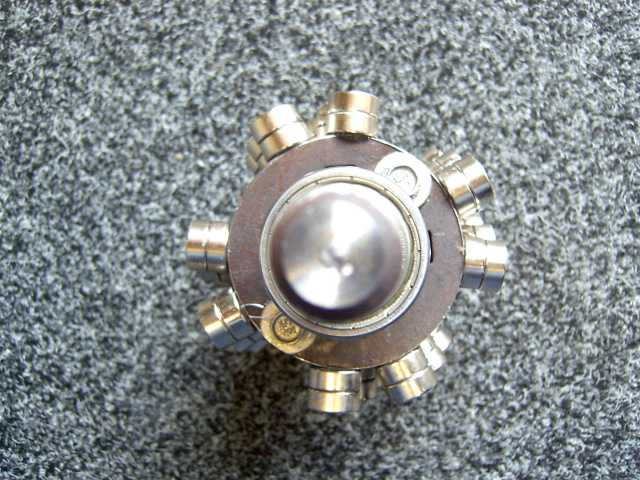
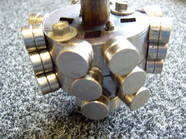
Here is a series of pics, where you can also see how I used the

roof screws again to stop the laminates from falling apart. Also

the magnets over hang the rotor a bit. I could have made a fresh

rotor but - bah, this is more of a toy for me :)


I keep all my old plastic, metal & glass containers these days.

They come in handy for so many things.
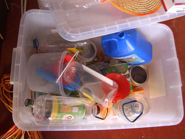


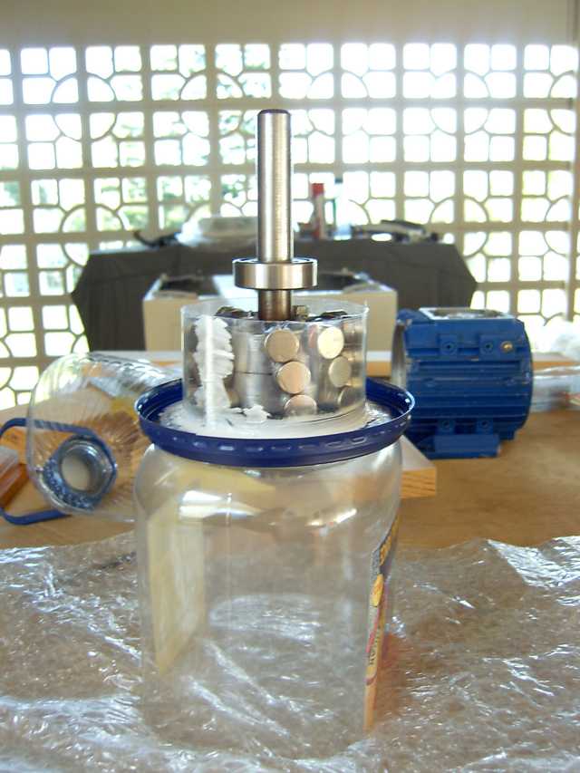
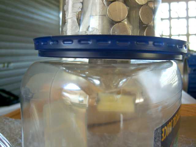
I sliced up an old juice container and wrapped it around the magnets.

Super glue joined it at the overlap. A plastic lid formed the bottom

of the mould, and good old silicone sealed all the gaps. You'll notice

I have not used a cage for the magnets. I want to push the new epoxy

to the limits :)


The rotor sat just nice inside the old juice container base.

Making it both a support and a spill container.


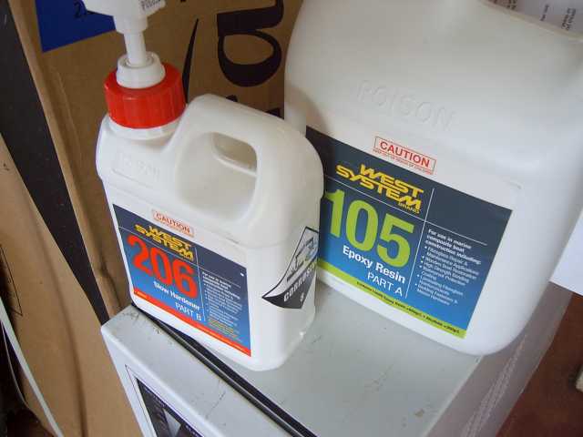
I bought some West System Epoxy this time, as I noticed a

lot of the forum use it. I'm using the 206 slow hardener,

as I'm a firm believer in a better cure for a slow cool/reaction.


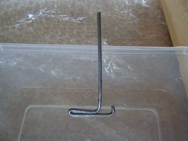
This is my patented :-) epoxy mixing tool. As you can see,

it was not engineered on a CAD system.


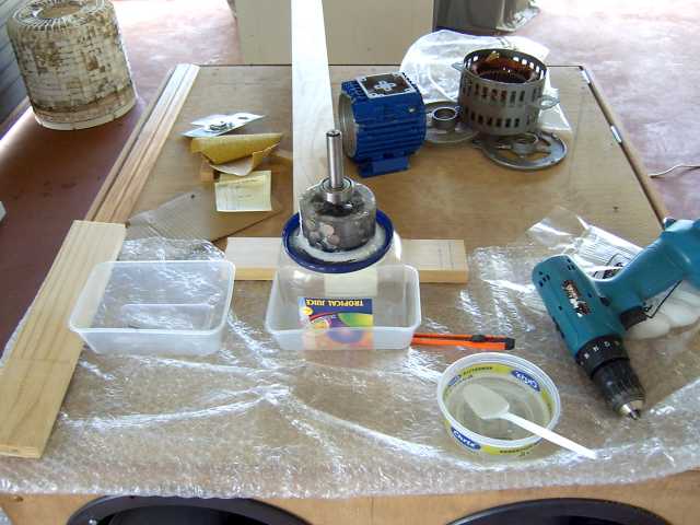
I use an old 12V drill connected to a 50Ahr battery for mixing

the epoxy. It means you never go flat in the middle of mixing,

or any other workshop job for that matter :-)


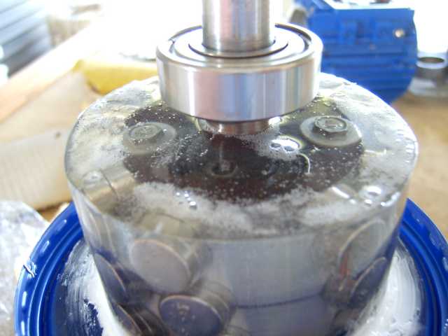
Here is the rotor about 30 minutes after being poured with epoxy.

Most of the bubbles have risen to the top, and formed a froth layer.


After curing for a week in our tropical sun, I put the rotor back

into the lathe and cleaned up the epoxy. The silicone and old

plastic container bits were peeled off easily by hand.
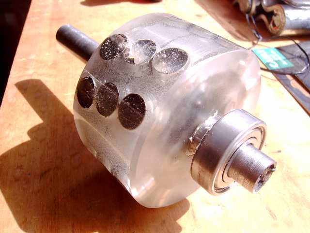


Here it is with the sun behind it. You can see the magnets inside the epoxy.
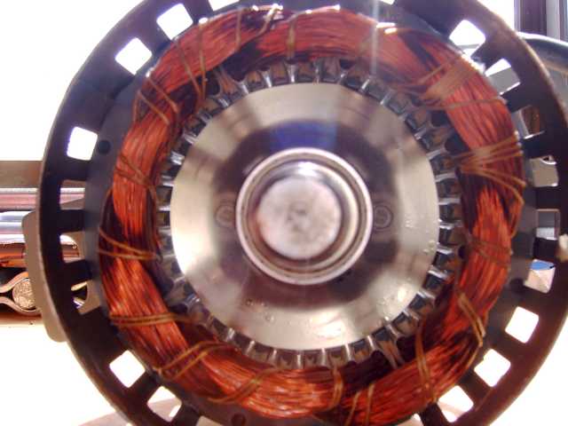


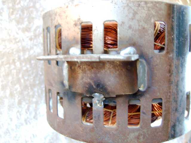
It has two new bearings, and I added some welds to the

mounting ears to make sure they don't break.


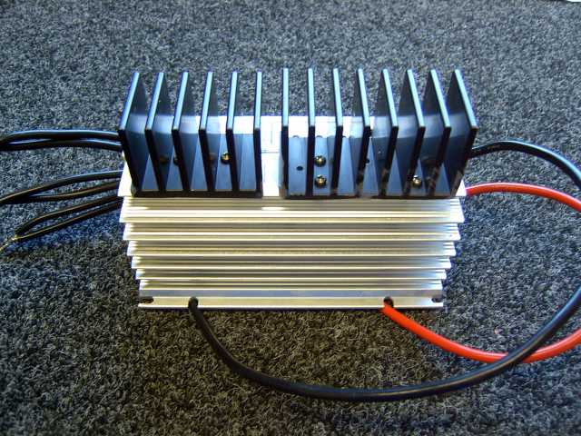
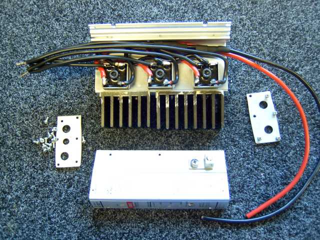
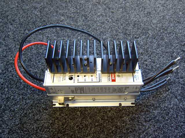
I used an old MATV amp to fit some 50Amp 600Volt bridge

rectifiers to. It was a good opportunity to play with the new

milling machine. I had to make a wider base for the bridges

to mount to, so a second MATV heatsink was cut down and

bolted to the main one. A 2-phase design has only to be treated

as if it were a 3-phase in regards to rectification. Its overkill,

but I have plenty of new bridges laying about.


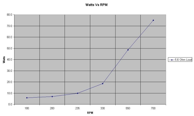
I put the motor back into the lathe and did some tests.

I knew from day one that this would not make much power

due to the 20ohm impedance of each winding. One thing I am

happy with is the waveform. Its an almost perfect sine wave.

The 3hp conversion I did earlier has a slight dip part way

through the wave. I suspect this is caused by a lack of magnets,

as I reduced the magnet count in the final stage of design. I hope

to get some digital waveform images soon.


The rotor can be spun between two fingers to produce 20+

Volts. It feels like a fine stepper motor when it's spun by hand.

I coated the windings with motor winding lacquer for use

in outdoor environments. And the whole outer casing got

a coat of my favourite 97% zinc protective Gal paint.


In conclusion, I'm happy that it performed as I expected it would.

It was a fun test project that produced more information for me

and tested my skills, so that makes it a success. I would call this

a 50-80watt alternator to be conservative. I don't think I could

get much more out of it with the stock windings. Considering that

it began life as a mass produced & average quality domestic motor,

worked for 12 years and then changed roles to produce power is

quite a heart warming thought :)


I'm going to do a set of wood blades based on Hugh's designs

and adjusted for higher RPM at lower (20-30klm/h) wind speeds.

About 800mm radius blades with a TSR of about 10 should do it.


I also recovered the "gearbox" from the washing machine, and

it seems to be about a 4:1 or thereabouts. It's a planetary style

with a sealed aluminium casing filled with oil, and brass/plastic

gears. I'm having kinky thoughts about using it as a speed up

for the motor - maybe get some serious RPM out of it. Curious,

the oil that was in the gearbox was squeaky clean after 12 years.


Spank me! The gearbox even has a friction brake!!

This is going to be fun  :)


I might set this one up at home in a suburban setting on a fold

over tube tower. It will be excellent for testing blades, MPPT

designs, my PICAXE LCD logger and generally gathering info.


If not, I can see it becoming a battery charger at a friends house

that has strong daily winds. He has a garden light system that runs

for a few hours a night. A full day of wind charging should handle

this no problem.


Costs:

Magnets  ~AU$15

Motor - free

Epoxy  ~ AU$5

New Bearings ~ AU$12

Rectifiers ~ AU$12

Heatsink - free

Total ~$44


Making power from junk - priceless :)


sPuDd..

« Last Edit: December 31, 2006, 04:05:32 AM by (unknown) »

Jerry

  • Hero Member
  • *****
  • Posts: 1519
Re: 3 phase.
« Reply #1 on: December 30, 2006, 10:25:43 PM »
Hi sPuDd.


Here are some thought for the 3 phase 2 pole you posted about earlyer.


Sorry for plcing it here but thought it might get over looked in that thred. It was geeting prety long?LOL


I've played with some 3 phase 2 pole conversions. If your not looking for much power and just expirimenting this might work as well as a group of small NEOs?


Also you might just concidering leaving the stock wireing in the next small 3 phase motor. Just seperate the ends of all coils. Perelell the coils of each phase, use a fullwave bridge for each phase then perelell the outputs of those 3 bridges.


Even though these magnets are only ceramics they cover allmost 100% of the pole face and because of this have practicaly no cogging. The output is low but on a par with the tinny NEOs.


Best part the ceramics are free. I get them from plumbers. Some of the Garbage disposal motor are PM and have a nice littel bridge rectifier also.


Heres a few pictures.


This last 1 is testing.


                     JK TAS Jerry

« Last Edit: December 30, 2006, 10:25:43 PM by Jerry »

sPuDd

  • Jr. Member
  • **
  • Posts: 51
Re: Washing Machine Induction Motor Conversion.
« Reply #2 on: December 31, 2006, 12:52:11 AM »
G'day Jerry,


    we don't get many sink waste units here. They don't seem

to be as popular as in other places. However - washing machines,

dryers and the like are quite common. Recently I picked up my

first two Fisher & Paykel smart drive motors off two retired

machines. At the same location were a dozen more machines

with regular induction motors. Industrial 3-phase  motors are

also pretty common here.


I also tend to look for the 4 pole or better motors, as I can get

more from them with less RPM. Also, I'm useless at rewiring

motors, so I look for ones that will not require anything more

than a few extra connections to make them star/delta.


But like I said, this little motor was just a play around thing.

It was that or it went to the dump like all our other precious

resources :-(  

Who knows, it might make an ideal charger for a permanent

roof top LED show :-)


sPuDd..

« Last Edit: December 31, 2006, 12:52:11 AM by sPuDd »

coldspot

  • Hero Member
  • *****
  • Posts: 843
  • Country: us
Re: 3 phase.
« Reply #3 on: December 31, 2006, 03:07:59 AM »
jerry-

Disposal motor-

Looks just like the "SinkMaster 401".

I scored last spring from under girlfriends sink!

   ( 1/3 HP, 115 Volts, 4.0 Amp, 1900 RPM,60 Hz, 1 PH) that turned out to be a DC motor run off AC with

"nice littel bridge rectifier" hidden inside, smallest square type I've seen so far!

Dam shaft I have left after major hard teardown, (was under sink broken for many years, rusted-up big time!), is just under a half inch long with weird left had threads and about .435 around.

Never flow yet, lack of blades and hubs!

But when tested with Voltmeter finger flipped, this baby was beating the heck out of-

A 24 VDC 300Watt scooter motor,

A 12 VDC "Simer Blue water pump,"536-951",

And a 32 VDC servo motor.

All these "Bad" DC motors would barly get to a single volt when finger flipped, but the sinkmaster,

6-8 volts easly and 10 once on a great flip.

Pretty bad bearings in mine, but still trying to figure out a hub n blade for it, (enlargening a hub shaft hole in a trim blade 4 blader I had, just destroyed the little metal hub, was 1/4" stock enlarged to 3/8" for servo motor, couldn't take 7/16".)

 :(

SpudD-

Not trying 2 jack your thread!

Your Magnet rotor with the exopy is best I've seen yet!

wow, great work!, (Now I'll have to add more epoxy to my 2HP's, because I've seen a better way now)

My 2HP, 3PH units with 8 #29's on rotor seem to have plenty of juice, just finger flip testing with mm and tail light bulbs. (Magnets from "nothingtoloose", forum member here).

:)

« Last Edit: December 31, 2006, 03:07:59 AM by coldspot »
$0.02

electrondady1

  • SuperHero Member
  • ******
  • Posts: 3122
  • Country: ca
Re: Washing Machine Induction Motor Conversion.
« Reply #4 on: December 31, 2006, 09:07:56 AM »
spudd, thanks for posting this project

nicely documented and photographed.
« Last Edit: December 31, 2006, 09:07:56 AM by electrondady1 »

sPuDd

  • Jr. Member
  • **
  • Posts: 51
Induction Motor Conversion - use as a motor again?
« Reply #5 on: December 31, 2006, 06:05:52 PM »
This is for Jerry and Zubbly and the other motor guys:


I was going to ask this question under the posting section,

but I can't find a suitable heading to put it under. As I've

just posted this diary entry, its probably more relevant here

anyway.


Question 1:

If an induction motor such as the one above had its rotor

converted from steel laminate to permanent magnets, could

the motor be used as a motor again? Assuming the conversion

did not affect the coils, and the magnets were arranged with

correct skew and pole count.


Reason I ask, is I'd like to modify a 3-phase induction motor

to permanent magnet rotor for use in an electric vehicle. If I

can drive it as a motor AND use it to regenerate power on

braking, it would mean a simplified design, reduced cost,

greater reliability and lower weight.


Question 2:

If the motor can be converted AND still used as a motor, it

raises more questions. Would the motor be more powerful

now that the coil fields are pushing magnets Vs pushing steel

laminates?


Thankyou in advance,


sPuDd..

« Last Edit: December 31, 2006, 06:05:52 PM by sPuDd »

ghurd

  • Super Hero Member Plus
  • *******
  • Posts: 8059
Re: Washing Machine Induction Motor Conversion.
« Reply #6 on: December 31, 2006, 06:46:27 PM »
Cool!

Nice job getting the magnets placed.  How did you hold them down for the initial gluing?


Have you considered reconnecting the coils in parallel?  It looks easier than most of my US motors, which like Jerry's photo, seem almost like a single chunk of coil.  :(

G-

« Last Edit: December 31, 2006, 06:46:27 PM by ghurd »
www.ghurd.info<<<-----Information on my Controller

Countryboy

  • Sr. Member
  • ****
  • Posts: 269
Re: Induction Motor Conversion - use as a motor ag
« Reply #7 on: December 31, 2006, 07:50:00 PM »
Hi Spudd,

  The first thing that comes to my mind is that a DC motor will act like a genny.  You can use DC motors as gennys - but you need to place a blocking diode in the wire between the battery and the motor.  Otherwise, if the wind stops spinning your blades, the current will reverse and the motor will start spinning the blades.


You could rig up a DC motor for a vehicle with some sort of diode hooked in with the brake system.  When you hit the brakes, the diode blocks power from the batteries, but still allows the motor to do some regenerative charging during braking.

« Last Edit: December 31, 2006, 07:50:00 PM by Countryboy »

Flux

  • Super Hero Member Plus
  • *******
  • Posts: 6275
Re: Induction Motor Conversion - use as a motor ag
« Reply #8 on: January 01, 2007, 01:47:45 AM »
If you convert an induction motor by adding magnets, then you turn it into a synchronous machine. It will then run as a synchronous alternator instead of an induction one. As a motor it will be limited to running synchronous at a fixed speed depending on the supply frequency and will probably be bad natured.


Alternatively you can add a rectifier and use it to generate dc. With suitable forced commutated rectifier technology it could be run as a motor from dc just as any other ECM dc motor, but the drive technology is not simple. Power will not be much different with magnets but you should be able to produce higher torque at low speed.


This is not a simple undertaking, don't be fooled into thinking that you can just run it as a motor or generator with a rectifier bridge.

Flux

« Last Edit: January 01, 2007, 01:47:45 AM by Flux »

dinges

  • Hero Member
  • *****
  • Posts: 1294
  • Country: nl
Re: Washing Machine Induction Motor Conversion.
« Reply #9 on: January 01, 2007, 01:51:43 AM »
Good job Spudd.


I have a few washing motors lying around but they're pretty small motors (though from 'normal' washing machines): 1/6 hp.


I had read before about how Zubbly did conversions using epoxy. Having read your story, I feel like using that technique too for one or two small conversions. For the big ones I'll stick with an aluminium sleeve & milled pockets, but the epoxy method certainly has its benefits too. Positioning the magnets by hand seems to have worked pretty good too. I understand you can still feel a hint of cogging, but it will not hamper start-up performance. Well done!


Is it my imagination, or do I see the next (blue) victim in the background of one of your pictures? Apparently it's already taken apart... :)


Naughty boy. You definitely need a good spanking for turning motors into generators.

« Last Edit: January 01, 2007, 01:51:43 AM by dinges »
“Research is what I'm doing when I don't know what I'm doing.” (W. von Braun)

sPuDd

  • Jr. Member
  • **
  • Posts: 51
Re: Washing Machine Induction Motor Conversion.
« Reply #10 on: January 01, 2007, 01:54:13 AM »
Ghurd,


   I placed each magnet on the rotor after putting a drop

of "not so super glue" on each one. Lets just say the acetone

came in handy several times. I'd hold each one for a few seconds

till the glue took over. That was it. Then it was ready for epoxy.


I searched for the coil join halfway connection - but I suspect it

was buried deeper than I wished to go without damaging the coils.

As it was I had to coat a few sections again due to scratching.


sPuDd..


« Last Edit: January 01, 2007, 01:54:13 AM by sPuDd »

sPuDd

  • Jr. Member
  • **
  • Posts: 51
Re: Washing Machine Induction Motor Conversion.
« Reply #11 on: January 01, 2007, 02:59:36 AM »
Hi Ho Dinges,

     thanks for the positive comments :)


The "Blue Victim" in the background is just that. I have already

had a shot at it as you will see in this diary posting:


http://www.fieldlines.com/story/2006/6/23/94016/5550


It didn't quite go to plan...  but at least I found my strengths

and weaknesses.


Flux,

     I'm in the process of putting together a VFD to drive stock

shelf 3-phase motors for the EV. Incorporating the regen into

the AC motor would save me having to make a separate alternator.

I have the luxury of two 3-phase 3hp motors, one a PM conversion

and one is stock. I'll give them both a try and see how it goes.


My only real fear with the PM conversion is the magnets at full rotor

speed, which will be 200-300% over rated speed. They may fly off :)


sPuDd..

« Last Edit: January 01, 2007, 02:59:36 AM by sPuDd »

asheets

  • Sr. Member
  • ****
  • Posts: 368
Re: Washing Machine Induction Motor Conversion.
« Reply #12 on: January 01, 2007, 03:35:14 PM »
Out of curiosity, and way the hell off topic... what brand of washer was that?  I don't recognize the washer itself, but the motor looks like an old 1/2 HP A-18 Maytag...
« Last Edit: January 01, 2007, 03:35:14 PM by asheets »

sPuDd

  • Jr. Member
  • **
  • Posts: 51
Re: Washing Machine Induction Motor Conversion.
« Reply #13 on: January 01, 2007, 11:11:59 PM »
Hello Alan,

    it was a Simpson 4kg washer. Its been replaced by a Maytag 8kg.

Now does a full weeks worth in one load :)


sPuDd..

« Last Edit: January 01, 2007, 11:11:59 PM by sPuDd »

tecker

  • SuperHero Member
  • ******
  • Posts: 2183
Re: Washing Machine Induction Motor Conversion.
« Reply #14 on: January 02, 2007, 07:45:08 AM »
If it hand spins 20 plus volts the unit probably is getting over 160 v open  300 rpm .

see what voltage it will muster thru 100 ohm 200 watt resistor . If you can get it to hold 150 volt your in the park for 200 to 225 watts . Regulate that and your at 12 to 15 amps those motors will hold 3 amps at working voltage so it shouldn't get too hot. What I'm saying is dump the dc into a good sized cap and use a regulated supply to get the charging voltage . At 12 volts you can't get that much thru but if the coils charge up high enough she gets the hammer out.
« Last Edit: January 02, 2007, 07:45:08 AM by tecker »

tecker

  • SuperHero Member
  • ******
  • Posts: 2183
Re: Washing Machine Induction Motor Conversion.
« Reply #15 on: January 04, 2007, 02:15:10 AM »
In looking at the blue motor I can see the insulators were cut even with the to of the core . I made a similar mistake with several stator before waking up to the fact that .

the coil ends have to be away from the core by at least 3/8 inch. when AI made that adjustment voltage went way up and I got rid of the dip in the wave form at the peak.

( dead giveaway ). I had low voltage with that dip with the coil end wound tight at the top of the core . I now use a wood spacer at he top and bottom to give that 3/8 inch now . Good returns on the stators now.
« Last Edit: January 04, 2007, 02:15:10 AM by tecker »

sPuDd

  • Jr. Member
  • **
  • Posts: 51
Re: Washing Machine Induction Motor Conversion.
« Reply #16 on: January 04, 2007, 05:54:38 PM »
G'day tecker,


     I'd say that would amount to a PWM or MPPT system if anything.

I see the reasoning in your maths, but I'm not sure how or if it would

be possible to maintain a high impedance at the front of the converter

while extracting large amounts of power at the output...  It might be

quite possible. It sounds like MPPT in theory. Its certainly got me

thinking. Hmmm, maybe some of the other board members have a

thought on the subject?


sPuDd..

« Last Edit: January 04, 2007, 05:54:38 PM by sPuDd »

tecker

  • SuperHero Member
  • ******
  • Posts: 2183
Re: Washing Machine Induction Motor Conversion.
« Reply #17 on: January 04, 2007, 06:37:43 PM »
Not really that complexed .You just hold the voltage up with a cap and load a dc to dc supply and charge the batts.  
« Last Edit: January 04, 2007, 06:37:43 PM by tecker »