Author Topic: Three cylinder version template  (Read 8695 times)

0 Members and 1 Guest are viewing this topic.

rotornuts

  • Hero Member
  • *****
  • Posts: 537
Three cylinder version template
« on: June 11, 2005, 02:27:37 AM »
I had no idea that post would generate so much interest so I don't mean to monopolize diary space but I'll start this over with an invitation to all interested to build one and see what kind of results you get. I have no equipment to generate hard data so maybe my perspective is skewed or I'm out to lunch.


This is purely experimental at this point so making one is for fun and at your own risk. I suggest you keep it simple at first.


I apologize for not making the cylinders a convenient size, the notion escaped me till I was done. The image below is a scale replica of the three cylinder model of the two cylinder unit I made with the exception that this one has been streamlined. As of yet the skies the limit and there are no hard rules on proportion but I would suggest an aspect ratio of 2:1 hieght to diameter so for the template below the unit would be 14" tall and 7" diameter. As for the venturi size I was aiming for 1/2 the diameter of one cylinder spacing at the narrowest point. The template is out by about 3/16 too wide in the venturi but it's unimportant at this point as it could work better that way.


I made this using photoshop and did my best to center everything but it could be off a tincy bit but again that shouldn't matter. The black dot in the middle should be center and the red dots in the three cylinders should be thier respective centers.


Don't print the image from your browser screen unless your confident there will be no scaling. On my computer it comes out 5 1/4" from the browser screen when it should be 7". if you have image handling software such as photoshop or digital camera software right click the image save it and print it from there. Using photoshop it prints at 7" as it should.


Anyhow, there it is have fun and post your results.


Mike


I know it's not far away but here's a link to the other post. Caution to dialup users

http://www.fieldlines.com/story/2005/6/8/35115/51007

« Last Edit: June 11, 2005, 02:27:37 AM by (unknown) »

electrondady1

  • SuperHero Member
  • ******
  • Posts: 3120
  • Country: ca
Re: Three cylinder version template
« Reply #1 on: June 10, 2005, 09:07:53 PM »
hey ! i just requested this image in the old diary, thanks a lot, are the dia. of the pillars arbitrary, have you experimented with different dia.s  yet?also to what extent have you explored the width of the vanes.?  ( i think that would be condidered the cord) and related to that in terms of what i believe is refered to as solidity,  is there a percentage considered to be optimum?
« Last Edit: June 10, 2005, 09:07:53 PM by electrondady1 »

jimjjnn

  • Hero Member
  • *****
  • Posts: 511
Re: Three cylinder version template
« Reply #2 on: June 10, 2005, 09:18:46 PM »
If out to lunch or skewed thinking, you are having fun and I applaud you for the way you are doing this project and all the great comments you are getting. GO FOR IT and ENJOY!!!!!

I am waiting to see how it goes. This kind of experimentation is needed
« Last Edit: June 10, 2005, 09:18:46 PM by jimjjnn »

rotornuts

  • Hero Member
  • *****
  • Posts: 537
Re: Three cylinder version template
« Reply #3 on: June 10, 2005, 09:49:49 PM »
No rules yet, This is just a starting point. I wouldn't rule out the two cylinder version either. I built this using proportions that seemed right, no hard science. As far a playing with the proportions I think the narrower the cord the faster it may run but with potentially lees torque except at higher rpms than a wider cord can attain. So far the narrower cords are working better. As for the diameter of the cylinder I'd be inclined to maybe make them a bit bigger which would give a little less space in between but thats for experimenting yet, could be the wrong way but I don't think so. The cylinder is a 71.5%ish thick airfoil with a round leading edge from the max thickness location, max thickness location 36%ish, cambered to allow the top of the profile to follow the circumference of the outer rim or something like that. Solidity is around 54.5%. I like the low wind perfomance of the three blader but I think something may be getting lost by adding another cylinder, not sure yet.


Mike

« Last Edit: June 10, 2005, 09:49:49 PM by rotornuts »

electrondady1

  • SuperHero Member
  • ******
  • Posts: 3120
  • Country: ca
Re: Three cylinder version template
« Reply #4 on: June 10, 2005, 09:53:19 PM »
also, roto, have you tried a streamlined version yet ? just thinking  about the the convex radius
« Last Edit: June 10, 2005, 09:53:19 PM by electrondady1 »

rotornuts

  • Hero Member
  • *****
  • Posts: 537
Re: Three cylinder version template
« Reply #5 on: June 10, 2005, 10:34:56 PM »
Nope, but I'm quite sure it will work better.


Mike

« Last Edit: June 10, 2005, 10:34:56 PM by rotornuts »

zap

  • Hero Member
  • *****
  • Posts: 1107
  • There's an app for that
Re: Three cylinder version template
« Reply #6 on: June 11, 2005, 10:04:14 AM »
Nice designs and some very good work Mike.


FYI: The image printed @ 7 ¼" @ default using PSP 7, no biggie I'm sure.


Keep up the fun work.

« Last Edit: June 11, 2005, 10:04:14 AM by zap »

rotornuts

  • Hero Member
  • *****
  • Posts: 537
Re: Three cylinder version template
« Reply #7 on: June 11, 2005, 11:33:28 AM »
I don't really undersdtand how that kind of thing works but I use PSP 7 as well. Oh well, it doesn't matter as long as it didn't distort the circle or make it too small(which it didn't of course)


I made it 72ppi which I believe is a standards display and print size so after that I don't know how to make sure everyone gets it the same size.


Have fun with it.


Mike

« Last Edit: June 11, 2005, 11:33:28 AM by rotornuts »

wildbill hickup

  • Full Member
  • ***
  • Posts: 183
Re: Three cylinder version template
« Reply #8 on: June 11, 2005, 01:28:21 PM »
Well got it done. It's not exactly like your drawing, more along the lines of you first pic in first post. Don't have any photos yet. No data either, you guessed it, all built and no wind, next 3 days light and variable, I hate when that happens. Now I sit in suspence for the next 3 days.


Well here is what I built. 10" diameter, 24" tall, each tube(3 of them) is 3" in diameter and the wings are about 4" wide. The biggest change I made was eliminating the center shaft, instead I ran allthread up through the center of each tube(hope it doesn't wobble. Seems pretty straight. Base is connected to an Ametec motor. Well here I sit waiting for the wind (I'm sick of spinning it by hand). It always blows up here on the hill except when I build a new jenny.


I'll get some pixs together and hopefully some data and report back in my diary.


Just havin' to much fun


Wildbill

« Last Edit: June 11, 2005, 01:28:21 PM by wildbill hickup »

rotornuts

  • Hero Member
  • *****
  • Posts: 537
Re: Three cylinder version template
« Reply #9 on: June 11, 2005, 11:25:15 PM »
Well I really hope it works well for ya. You'll be the first to produce power with it. I think eliminating the center shaft is a good thing if you can make the base strong enough to take the bending torque. The 3" tubes may be a bit small on a 10' disk, as a comparison if you relate the 2.5" tube on the model to the disk diameter you get 93% disk diameter to combined tube diameters and on yours you get 111% disk to combined tube diameters. Your sizing may work better and I'm curious to see your results. I'll be doing the wind dance for you tonight. You may also just for comparisons sake want to try a smaller flap. Again I can'r say if a shorter flap is better but on my models I was getting better rpm with a 1:1 ratio on tube diameter to flap length but it may yield lower torque which I couldn't test so again I'd be curious.


I eagerly await your results good or bad, but of course they'll be good, right!


Mike

« Last Edit: June 11, 2005, 11:25:15 PM by rotornuts »

wildbill hickup

  • Full Member
  • ***
  • Posts: 183
Re: Three cylinder version template
« Reply #10 on: June 12, 2005, 06:17:47 AM »
Well I appriciated the wind dance, nothin' yet (please dance harder):-> I used the 3" tubes cause they were all I had at the time, it gives me a starting point anyway well that is when the wind blows. Wait I see the leaves moving ...... oh well false alarm, not even enough to turn the HAWT into the wind. Better go put this out though (it's a dry weather model so it came in last night) you never know. I'm also waiting to see if my 'no axle' idea works. I've already got a new idea if it doesn't, but have to give the first one a chance. Well still waitin' on the wind. I'll let you know how it goes!


Wildbill

« Last Edit: June 12, 2005, 06:17:47 AM by wildbill hickup »

wildbill hickup

  • Full Member
  • ***
  • Posts: 183
Re: Three cylinder version template
« Reply #11 on: June 12, 2005, 06:55:41 AM »
A question:


 " The 3" tubes may be a bit small on a 10' disk, as a comparison if you relate the 2.5" tube on the model to the disk diameter you get 93% disk diameter to combined tube diameters and on yours you get 111% disk to combined tube diameters. "


What is the formula you used to calculate these????


Wildbill

« Last Edit: June 12, 2005, 06:55:41 AM by wildbill hickup »

rotornuts

  • Hero Member
  • *****
  • Posts: 537
Re: Three cylinder version template
« Reply #12 on: June 12, 2005, 10:00:58 AM »
The disk diameter is 93% of the diameters of the three tubes added up. So add the diameters of your tubes and divide that by your disk diameter. (3X3)/10=1.11 or 111%

                                                               (2.5x2.5)/7=.93 or 93%


There are several things you could do to relate disk/tube sizes like comparing it to the circ. or just using the center opening size but they all tell the same story and are intimately related, if you change one the others will change as well. I'm just trying to record these relationships so we can see what works better. There is no magic formula there.


Sorry to taunt you but I got lots o wind today. Maybe I could mail you some?


Mike

« Last Edit: June 12, 2005, 10:00:58 AM by rotornuts »

electrondady1

  • SuperHero Member
  • ******
  • Posts: 3120
  • Country: ca
Re: Three cylinder version template
« Reply #13 on: June 12, 2005, 10:09:32 AM »
as far as i can see the dia. of the disk is secondary to the dia of the tubes and the relationship between them and there center points.
« Last Edit: June 12, 2005, 10:09:32 AM by electrondady1 »

electrondady1

  • SuperHero Member
  • ******
  • Posts: 3120
  • Country: ca
Re: Three cylinder version template
« Reply #14 on: June 12, 2005, 10:25:39 AM »
ok,  thats as clear as mud . what i'm trying to say is whatever the dia. of the tubes, its the relationship (distance) to the next tube that is signifigant. a slick way to  experiment with this configuration might be to construct a hub with three radial arms. each would possess multiple holes to anchor the tubes . the same procedure could be done using wooden disks if incremental centering holes were drilled along three radial lines .
« Last Edit: June 12, 2005, 10:25:39 AM by electrondady1 »

rotornuts

  • Hero Member
  • *****
  • Posts: 537
Re: Three cylinder version template
« Reply #15 on: June 12, 2005, 12:17:23 PM »
That's right electondady. The disk is secondary to the tube spacing but if you wish to increase tube size and maintain the relationship you have you of course need to increase the disk size. Your idea of providing additional mounting holes to play with the spacing would work really well but I would do that to the disk not arms as arms would create additional induced drag but the disk will not(not nearly as bad that is). there may be some interaction between the overhang and the flaps at smaller spacings but I can't see that as a problem.


Mike

« Last Edit: June 12, 2005, 12:17:23 PM by rotornuts »

rotornuts

  • Hero Member
  • *****
  • Posts: 537
Re: Three cylinder version template
« Reply #16 on: June 12, 2005, 01:14:43 PM »
I could be using flawed logic here but there is something else to consider when establishing the diameter of this thing and it's time. Unlike a hawt, vawt's blades don't produce power during 100% of it's revolution. At this point I can only say for sure that a single blade/airfoil(tube/flap combo)is producing power across the airflow at the front and back of the unit. To produce to each blades potential it requires time to accelerate to it's max potential. If the diameter of the unit as a whole is too small I think it's reasonable to say the airfoils will not reach thier max potential before they go into a dead zone where they produce little power or drag, they require the right diameter in relation to all the other factors to accelerate to thier max Cp. It's like furling a hawt at to low a wind speed. Conversely I think it's also reasonable to say if it's too large(diameter) then the blades will reach thier power potential and start to create unnessecary drag reducing efficiency(stall).


I believe there is a proper ratio of diameter to the other factors and I only say factors because they are numerous. We need to consider time as well when we think about these vawt's. If one wants additionall power it would be better to increase the height rather than diameter although doing so would likely require a small change in diameter as well. Hope that's clear as mud.


Mike

« Last Edit: June 12, 2005, 01:14:43 PM by rotornuts »

monte350c

  • Full Member
  • ***
  • Posts: 228
Re: Three cylinder version template
« Reply #17 on: June 12, 2005, 02:13:53 PM »
Hi Mike,


I think you're going down the right path with the VAWT research. It's not the same kettle of fish as the HAWT units.


I hope there's a future for the verticals, and there might be for some applications.


It IS interesting to note that the power all happens at the front and at the back of the rotor plane.


I keep wondering if there's something that can be done to help widen out the power production band...


Here's a couple of graphs I copied from Dr. Gary Johnson's book, they're on the 17 meter Sandia Darrieus operating at 50 rpm.


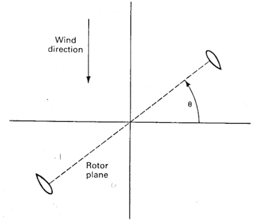
First the definition of rotor angle:


and the relative power output vs. rotor angle:


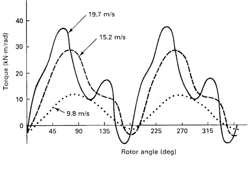
There's a pretty obvious torque ripple all right.


The unit is bound to be affected by its aspect ratio, rotational speed, solidity, and number of blades (or cylinders etc.). A change to any of these will probably have an effect on the others.


Lots of fun!


Ted.

« Last Edit: June 12, 2005, 02:13:53 PM by monte350c »

rotornuts

  • Hero Member
  • *****
  • Posts: 537
Re: Three cylinder version template
« Reply #18 on: June 12, 2005, 03:46:13 PM »
Thanks for the graph Ted. I'd like to even try to eliminate the portions of the graph where the torque fiqure dips into the negative numbers.


It seems that the best torque is produced when one of the blades is at about 70 degrees flying into the wind. I think the short power band is due to profiles that have a low range of AoA's where they perform well.


The cylindrical profiles while they have a high drag coefficient also perform over a very wide range of AoA's, I think part of the reason the narrower cords have been performing better is that they allow for utilization of more of the leading edge of the cylinder to produce lift. Cylinders I think also allow for a smoother transition from lift being produce on the outside of the profile to the inside of the profile. There is still a big problem with the 3 and 9 O'clock positions and how to increase the performance in that area. The only way I can see improving that is to try savy methods of flow manipulation to try and change the direction of the appearant wind during that part of the rotation. This is the reason I put two cylinders so close to each other with this experiment. I don't think it worked like I was hoping but I think there's been an improvement. By playing the airflow off one cylinder to present it at a different angle to the other in the areas of rotation where we see the Torque figures drop to almost nothing maybe we can eliminate some of the torque ripple and increase power production.


The catch 22 is making it so that flow manipulations present one way at the 3 o'clock position without doing the same thing at the same time on the 9 o'clock side cancelling the gain. That's part of the reason I was skeptical about adding another cylinder. I was having a hard time visualizing what was giong to happen to the flow through the center but in the end I think it presents better opportunites to do what I'm hoping for.


This is a nasty challenge but I like to maintain hope there's a good solution without resorting to extravagant mechanical devices.


Mike

« Last Edit: June 12, 2005, 03:46:13 PM by rotornuts »

ghurd

  • Super Hero Member Plus
  • *******
  • Posts: 8059
Re: Three cylinder version template
« Reply #19 on: June 12, 2005, 03:55:54 PM »
The high torque and negative torque peaks are quite narrow.

Add another set of cylinders offset above the first.

The peaks should then cancel each other maintaining a more stable output (?).

Maybe less vibration (?).


I have no idea what I'm talking about, just seems like it would work.

Following this closely.

G-

« Last Edit: June 12, 2005, 03:55:54 PM by ghurd »
www.ghurd.info<<<-----Information on my Controller

monte350c

  • Full Member
  • ***
  • Posts: 228
Re: Three cylinder version template
« Reply #20 on: June 12, 2005, 04:41:06 PM »
Hi Mike,


The angle of attack - apparent AOA that is, on the profiles in use in those days (ie NACA0012, 0015 etc) is fairly narrow, the primary stall occurring at something like 15 degrees or less.


So if you follow the torque curves around, by inference off the chart, and where the stall is, you can see where the apparent wind is with respect to the blade.


That idea does lead to some interesting thoughts - how to use different profiles with different stall behaviour, or how to manipulate the apparent wind to get the results. Good stuff!


Ted.

« Last Edit: June 12, 2005, 04:41:06 PM by monte350c »

electrondady1

  • SuperHero Member
  • ******
  • Posts: 3120
  • Country: ca
Re: Three cylinder version template
« Reply #21 on: June 12, 2005, 06:22:22 PM »
makes sense to me gurd. what i find intreaging is, with three pillars  at any one time ( well at three seperate times per rotation) you have two outlets for the venturi effect  to channel through.
« Last Edit: June 12, 2005, 06:22:22 PM by electrondady1 »

wdyasq

  • Hero Member
  • *****
  • Posts: 1324
A new tack
« Reply #22 on: June 12, 2005, 07:17:13 PM »
As I don't have a dog in this hunt, maybe I shouldn't get in the fray. A look at the Gorlov turbine shows how he solved some of the problems.  If 'I' were making one of these (and I'm not), I might try a hybred of the Gorlov and a straight rotor by using two or three angled blades on one turbine.  It would get similar lift figures to the true helix Gorlov suggests but would be easy to model and build.  


It could have two or three airfoils and two or three sections.  The airfoil root on a bottom disc would start/finish where a the top one finished/started . This method would expose complete airfoild sections to similar forces to similar power bands and all but eliminate the torque ripple shown. A triangular brace would be all that is needed at the mid/third/quarter point intersections.


My description is probably clear as a government document.


Ron

« Last Edit: June 12, 2005, 07:17:13 PM by wdyasq »
"I like the Honey, but kill the bees"

monte350c

  • Full Member
  • ***
  • Posts: 228
Re: A new tack
« Reply #23 on: June 12, 2005, 07:37:09 PM »
Your description is fine. And that's a heck of a good idea too. Wonder why Gorlov isn't doing wind?


http://www.gcktechnology.com/


Ted.

« Last Edit: June 12, 2005, 07:37:09 PM by monte350c »

ghurd

  • Super Hero Member Plus
  • *******
  • Posts: 8059
Re: Three cylinder version template
« Reply #24 on: June 12, 2005, 11:15:12 PM »
I'll be formal.


Dear Sir,

You must have mistaken me for someone who actually understands 20% of this topic! :)


It just seemed like about 3 seperate sections at about 35% height of the graph cylinders would be a more stabile output of decent characteristics.


This is beyond my currant comprehension, but I'm trying.


(I spent part of today bandsawing bad window fan blades, which was a failure, they worked no better than before, maybe even worse)

G-

« Last Edit: June 12, 2005, 11:15:12 PM by ghurd »
www.ghurd.info<<<-----Information on my Controller

electrondady1

  • SuperHero Member
  • ******
  • Posts: 3120
  • Country: ca
Re: Three cylinder version template
« Reply #25 on: June 13, 2005, 06:44:37 AM »
whats going on here is clever thief rotonuts is trying to steal power twice from the same wind.ha ha  inspired by the notorius windstuff ed (who steals power from the wind on a routine basis) roto has taken a conventional drag layout and turned it into a modified darius. by using an unconventional shape for the darius wings, he is now attempting to control/manipulate the air passing through the interior of this device.forcing even more power from the poor wind! stay tuned for the next episode as roto's minions contrbute there own wicked ideas!
« Last Edit: June 13, 2005, 06:44:37 AM by electrondady1 »

electrondady1

  • SuperHero Member
  • ******
  • Posts: 3120
  • Country: ca
Re: A new tack
« Reply #26 on: June 15, 2005, 07:56:17 AM »
well, nobody liked the series script. best talk about the layout of this geni. roto i've been thinking about what you were saying about time/ rotational speed . on the down side of the venturi you have two outlets at any one time. but these are constantly being replaced as the unit rotates. do you think the center eventually becomes dead air at higher rpm?
« Last Edit: June 15, 2005, 07:56:17 AM by electrondady1 »

rotornuts

  • Hero Member
  • *****
  • Posts: 537
Re: A new tack
« Reply #27 on: June 15, 2005, 09:19:35 AM »
Yes I think it does in a way. I did some tests with mine using a blow dryer and it will rotate clockwise if you blow through the center but it doesn't gain much speed because the center becomes obstructed by the 3 0'clock cylinder. The center is only providing short pulses and at higher speeds if you shift the air flow to the center again you can still feel some pulsing although it's slight. I'm thinking in this configuration(streamlined cylinders) the two blade version is maybe better as the center remains open longer. I think the three cylinder is basicly a streamlined savionus.


The blade that is in the 2-4 o'clock position is still presenting alot of drag and that hurts performance although as rpm increases the drag figure goes down because of the drag characteristics of a cylinder and the fact that pressure is building in the center shedding air around the outside of the unit rather than through it. At that point pretty much all the rotational energy is being generated from the 6 - 11 or 12 o'clock position but that's not bad because the unit is starting to gain some "appearent" solidity so the stagnation points have likely moved to the 5 and 2 o'clock positions, that is if one exists on the backside. The air that is moving around the left side will be doing so at around 2 times the speed of the upstream air flow so there is alot of energy that can be extracted.


A solution is needed to enable the 2-4 o'clock position to become a net contributor without just "pushing" it through with other blades, by doing that we would be ignoring the power loss due to drag and would likely be no further ahead.


The problem: how do you get a wing to fly into the wind hanging on the end of a lever that is fixed to a point in the center of rotation.


I have another idea  that may render the problem area a very minor contributor but I'm still looking it over. No matter what there will always be a drag only point as the blade transitions from producing lift on it's outside surface to it's inside surface. That ones not going away.


I still thing this thing is maybe a bit more efficient than a three blade savionus but with less start torque.

« Last Edit: June 15, 2005, 09:19:35 AM by rotornuts »

TomW

  • Super Hero Member Plus
  • *******
  • Posts: 5130
  • Country: us
Re: A new tack
« Reply #28 on: June 15, 2005, 09:35:39 AM »
Nutz;


Most of this is well beyond me but while reading thru this stuff I had a thought [scary I know]. I wondered if you could alter the foils shape somehow rather than flipping it around or whatever? Not sure how you could do this but the idea included a tail similar to windstuff Eds design from awhile back. The linkage might activate cams or something inside a flexible skin to shift the cross section of the foil from one side to the other. Probably lunacy and unworkable but just thought I would toss that into the blender.


I have always thought the VAWT could be made to work well and that it suffered ongoing prejudice and misrepresentation due to historic inaccurate data.


Cheers.


TomW

« Last Edit: June 15, 2005, 09:35:39 AM by TomW »

windstuffnow

  • Hero Member
  • *****
  • Posts: 1065
  • Country: 00
Re: A new tack
« Reply #29 on: June 15, 2005, 10:44:11 AM »
"The problem: how do you get a wing to fly into the wind hanging on the end of a lever that is fixed to a point in the center of rotation."


  Airplanes do this all the time, althought the (ficticious) piviot point is much larger.  I've done alot of experimenting with wings on the upwind side and a few dozen machines of varying  success and failure.  Getting a wing to "fly" on the up wind side really isn't a major problem and the power is quite impressive.  The real problem is setting the wing angle to represent maximum lift at any given point through the 180 of the up  wind side.  All the successful models had a full drop in power at the 90 degree transition point.  They did however pull themselves to that point and once beyond carried it to and beyond the 0 point.


After calculating what was going on in a drag machine it was easy to see all the power wasted on the up wind side.  Since downwind blade only really sees a small portion of the actual wind ( because its moving away from the wind ) the up wind side sees the wind plus the rotor speed.  If the wind speed is say 10 mph and the rotor is running at a TSR of 2 then the up wind blade actually sees a 30mph wind.  That will produce a massive amount of lift but similar to a drag machine the downwind blade sees a much smaller portion of that so it seems to be a give and take ( one side or the other ).  The tail driven cam is one successful way of harnessing the upwind side, and also, when exadurated, increases efficiency of the downwind side for a drag machine.  It still has its failing "spots" during rotation.  This is where I am at this point, my conclusions led me to the one I'm working on now ( when I can get back to it ).  This new one by no means falls into the "KISS" catagory.  I believe to maintain "KISS" you ultimately have to give up some portion of power through its rotation.  You can change it but although you gain a portion at that angle you also give something up at another, therefore, you need to add something to alter the flat spots (i.e. controls ).


Lots of fun though! Back to finishing some alternators so I can ultimately get back to playing...

« Last Edit: June 15, 2005, 10:44:11 AM by windstuffnow »
Windstuff Ed

electrondady1

  • SuperHero Member
  • ******
  • Posts: 3120
  • Country: ca
Re: A new tack
« Reply #30 on: June 15, 2005, 11:05:25 AM »
if you have one passage for the entering /exiting air flow that reverses position/direction every 180 deg. your going to be fighting the enertia of the air itself . thats what i thought the advantage of more pasages/airfoil elements was . although the flow direction is always in transition it never has to actually stop .
« Last Edit: June 15, 2005, 11:05:25 AM by electrondady1 »

rotornuts

  • Hero Member
  • *****
  • Posts: 537
Re: A new tack
« Reply #31 on: June 15, 2005, 12:13:02 PM »
Hello again.


I'm resigned to the fact that the only way to fly a wing upwind is to alter AOA through the rotation. Below is a simple illustration.


Anyway it's easy to see that the resolved lift vector at a constant AOA or 0 degrees across the 3 o'clock position results in the force being applied behind the axis resulting in reversed rotation.


Now as you said if we alter the AOA to a favorable angle at any given point in the rotation we can extract usable rotational energy through nearly all but the 3 o'clock nieghbourhood. This of course is the reason most efforts are to devise an efficient mechanism for this and I'm confident with your mechanical savy Ed you will be successfull and I'm eager to see the result of your latest experiment.


I on the other hand I tend to try things the hard way(not to say there are easy solutions for these things). I'm hoping that somehow I can take advantage of the upwind 3-6 o'clock position without pitch control and ruining the rest of the cycle. I think it's like an overunity thing and unlikely to happen. It seems as soon as you do something to improve the upwind side of the cycle it adversly effects the other portions of the cycle.


Anyhow I'll show you another idea I was playing with last night. I haven't really analized it's sortcoming yet but here it is anyway.


The idea is to get some lifting surface into a favorable position as the slotted blade passes the 3 position. it also allows for the resultant lift being ahead of the axis slightly on the inboard surfaces once the retreating blade clears the oncoming wind.


or something like that.


Mike

« Last Edit: June 15, 2005, 12:13:02 PM by rotornuts »

windstuffnow

  • Hero Member
  • *****
  • Posts: 1065
  • Country: 00
Re: A new tack
« Reply #32 on: June 15, 2005, 01:48:10 PM »
  Thats an interesting idea... I see it in my mind reversed.  That is to say the larger wings would be set toward the center and they would loose chord width as they progressed to the outer edge.  Each would have its own unique AoA and as well each would be designed to run at its respective TSR based on its position in the circle.  That would be tricky to calculate.  Much easier to calculate a darrieus with a sav in the middle.


  I like where your going though, lots of real creative thinking!  I've found that many times by building the machine you'll find problems either before the machine is built or during testing and from there tons of ideas will filter in from the experience.  Sometimes an idea that pertains to one machine spawns hybrid ideas that can be used in conjunction with another to make it better in some way.


Lots of Fun!

« Last Edit: June 15, 2005, 01:48:10 PM by windstuffnow »
Windstuff Ed