Hello people - 1st diary entry here...
I am looking for the best output using 12 coil: 8 mag setup.
This Maytag switched reluctance motor came from a Sears warranty work dumpster & was just too cool to let get buried in a landfill. The Neos stuck onto the rotor like they were meant to be there - looks even cooler w/ neos on backing plate. The spring mount on the bearing I hope will help handle thrust forces
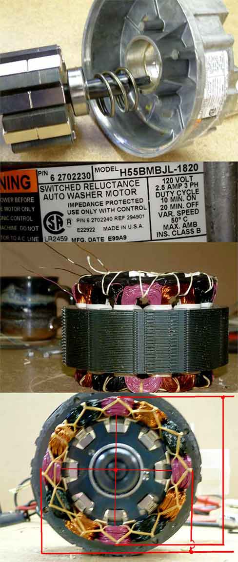
The last panel shows stock wiring configuration, "two sets" of "two paralleled coils" in series. Anyone see alternate arrangements using stock coils? I'll pull it apart and rewire if a consensus can be reached...
I know 2000 RPMs are too high, I'm procrastinating a rewind of coils to get wind cut-in speed - still experimenting before I learn how to duplicate & insert machine wound coils.
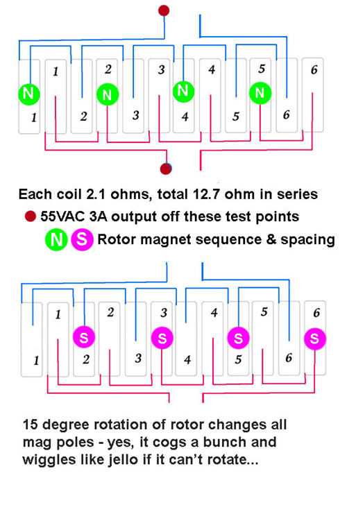
I wired as in diagram and get nothing on each series of coils, but between coil sets achieve good pure inductive output - coil sets are isolated from each other yet output 55VAC 3amp!
Am also thinking to use a 6" PVC or aluminum pipe to replace the laminated outer housing & coils w/ homemade air-core coils, and then probably have to mill down the rotor cogs at least down to the magnet backing plate.
- 3" rotor diameter.
- 3" coil lengths w/ laminate core 2.375".
- 2" long laminated 8-cog rotor core.
Magnets on iron backing plate w/ .375" gap between them.
1/16" air gap, magnet top edge level w/ cog faces.
Two 1" x 1/2" x 1/4" N38 mags per cog.
Mags are N-S-N-S on rotor, Coils are configured NS-NS-NS-NS.
- Yes the magnet gods laughed at me trying to bond N38's onto 1/2" wide backing plates, they crept and spun, overnight 1/8" creep etc. until I tried the 4-minute epoxy. Automotive weather striping adhesive, spray contact cement each gave a 50% failure rate assembling w/o a jig. The epoxy worked, which reminds me, much easier to have spent the extra $$$ and bought two-inch long mags instead of using two one-inch mags, but this is first time handling Neos and it was good practice - like three evenings wasted time though.
-Insertion of rotor into windings was impossible w/o epoxy; 1/16" air gap had all mags leaping onto coil laminate and locking up assembly and damaging mags. Easiest to remove coil housing, insert epoxied rotor and then attach end bells. It was even too tight for pepsi 2-litre bottle plastic guard sleeve trying to keep magnet weld down!
-Output before raising mags 1/8" (to match cog radius) via the iron backing plates was 38VAC 2A @2000rpm. Also gave 3/8" inch gap between the mags when fixing to backing.
-If you hold unit in hand and spin it, within a second you start to feel an electric shocks tingle. I don't know if its stray voltages or just vibration reminding me of the 60Hz AC tingle. Unit warns NOT to ground motor in OEM application.
-I'd like to see 125 watts from this; more likely the mags will be salvaged and reused though.
I'm worn out from long day & will post back when I remember what else I was supposed to post here 
