We were discusing the GM alt below in another diary. Thought I'd make a new diary about my 2 faced GM alt I did a couple years back. I think some of you were intrested?
I had been doing ac motor conversions at the time. I found that in some motors it was easyer to use an armature from a diferant motor rather then the original.
This is true of the Garbogen. When the old #29 curved NEOs are used in a garbage disposa motor conversion (now you know why its called the Garbogen) the original armature is way to short for the #29 magnets. Therefor I use an armature from a 6 pole furnace blower motors.
Because of this I've got quite a collection of garbage disposal motor armatures.
Now I dicided to try some mods to the GM alt. The original rotor in the GM alt has 14 fingers. Some folks have machined down the fingers a glude magnets directly to the fingers.
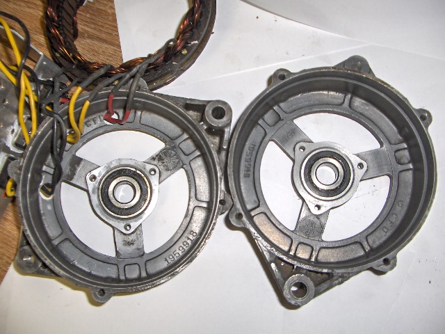
I went back to my idea of useing a diferant armature in the conversion. Hence the garbage disposal armature that had no other use. There shafts are short but just long enough for this conversion. The shaft is 5/8" in most. Problem is the GM alt has a diferant shaft size. The front bearing can be swaped out for the right size bearing but the rear bearing is part of the rear housing so no changing there.
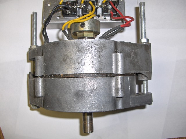
Works out it real easy to just use 2 GM alt fronts and replace the bearings to proper size.
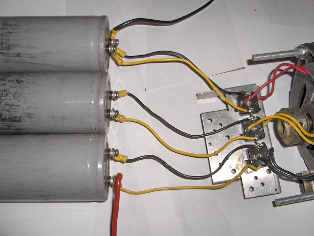
Next on this alt I wire all 3 phases to there own and seperate fullwave bridge diode and then wire the DC outputs of these diode bridges in sires. I also conected a large value elect. cap to the DC terminals of each bridge.
This is the way to get the highest voltage at the lowest rpm out of this GM car alt.
This voltage will be almost twice the voltage of star.
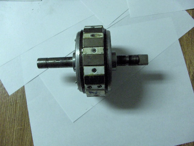
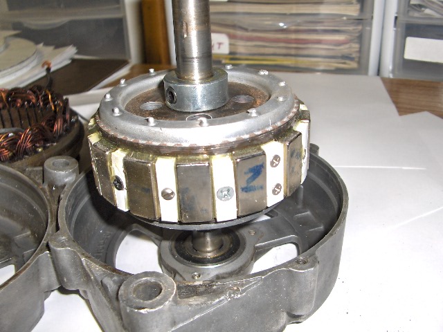
The Garbogen armature in this mod was fitted with 14 each 1"X 1/2"X 1/4" NEOs.
I used plastic spacers between the magnets. The spacers are screwed down with stainless stell screws and the magnets and spacers are glude with epoxi.
This armature coggs bad. I sugjest a dounught NEO in a stock armature is a better way. Power is a littel less but cogging is mild.
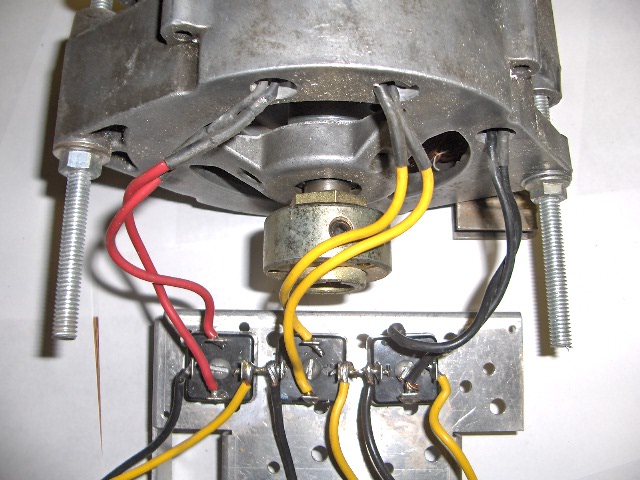
OK now a sires of pix. At the back of the alt you can see the seperate wires for each phase there collor coded to keep things correct.
You can just make out the sires jumpers between the dc part of the diode bridges. The plus and minus are taken off at the caps.
JK TAS Jerry
