In the beginning, my goal was to build a wind generator. I wanted to go in a different direction to see if I could come up with something different on my own. I think I did that. It was'nt the best set up, but I did try and that's what counts. After some critique and some thinking, I decided to go back to what I call a conventional design. anyway I learned alot from my design, how 3 phase works, coil design, calculating number of turns, ect.
I didn't feel the need to post alot of the work since it is the same as other people before me. So here's the stats:
- pole 9 coil design
- turns 15 ga. wire per coil
Star configuration
Stator 5/8" thick
1- 1/2"x 1" x 1/2" n40 neo's
The magnets are about 3/4" apart when assembled
Looks like I have just under 1 ohm resistance per phase.
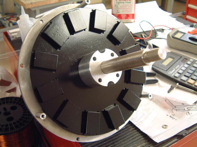
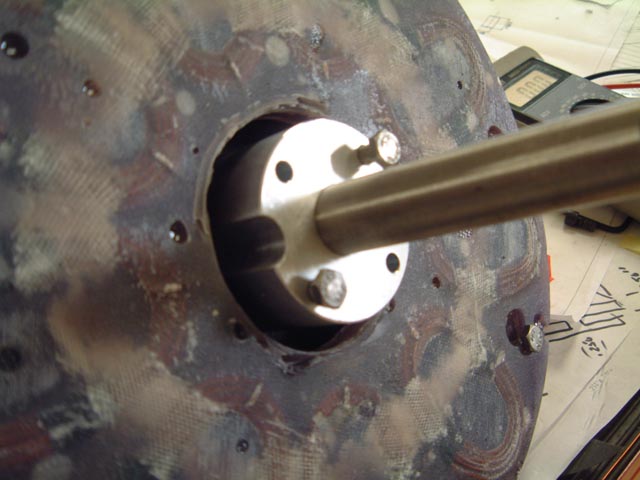
Here's a picture of my assembly going together.
The cut out in the spacer are for the jack screws. I forgot to make the inside hole in the stator big enough so I had to improvise.
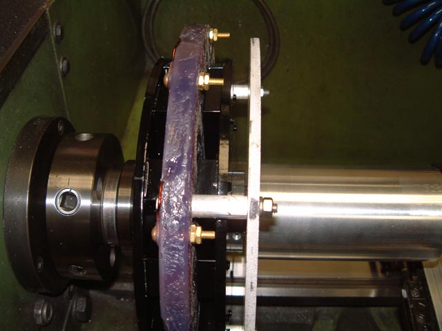
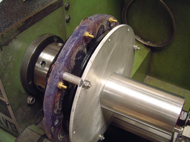
Here's a picture of the stator installed
After I completed the assembly I put it in the lathe for some initial tests.
Here are the open volt:
RPM to Volts
- is 6.5
- is 10.9
- is 15.6
- is 19.0
- is 27.2
- is 31.6
- is 53.9
- is 77.1
- is 91.7
- is 127.2
I don't know if this is good or not but seems reasonable to me. I made the holes in the coils about 15 percent bigger than the magnets. I hope this "links" the coils properly.
I'm going to do a load test next to see what king of amperage it will put out. I think I will connect 50 feet of wire to it and then rectify it to 12 volts and see if there is any drop in voltage from directly on the generator to the end of the wire. I know that I will loose some in the conversion to DC power. I am hoping the cut in will be a little higher RPM that I am Currently getting.
I was a little surprised that I am getting the voltage out of this with a smaller magnet than most people are using.
I will post the results of the amperage test next week.
That all for now.
