Author Topic: Homebrew PWM Power Supply, Tweaking?  (Read 2942 times)

0 Members and 2 Guests are viewing this topic.

Madscientist267

  • Hero Member
  • *****
  • Posts: 1181
  • Country: us
  • Uh oh. Now what have I done?
Homebrew PWM Power Supply, Tweaking?
« on: February 14, 2009, 07:59:53 AM »
This is a re-post; the original was rendered a surf-by, lost in the shuffle...


Anybody either have in their possession or know where a schematic for a power supply that outs +-32VDC at about 2A peak (~1A sustained) from a single 12V input?


Dot...Dot...Dot...


UPDATE:


While I got a few suggestions (some good), I ended up building one of my own conception, and it works great, but it seems a little power hungry.


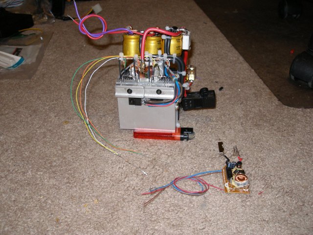
It uses a center tapped toroid and 2 sets of 2 IRFZ44N MOSFETs in push-pull, driven by a TL494 chip. I don't have a schematic just yet, as I basically modified a cell phone charger to use as a controller.


Test conditions are ~12.7V input, output is +/- 32.4V. MOSFET temp held to a nice and cool ~75 deg F (AMD Athlon 64 heatsink with the fan running full speed from a separate supply).


One concern seems to be that it draws ~350mA with only a ~50mA load, and at ~120W (4x60W light bulbs in parallel, rail to rail), it was blowing 15A fuses, and even stressing and then eventually blowing 20A. This just seems out of proportion.


I'm thinking the inefficiency is related to a resonance issue, as the toroid gets rather warm at 120W after 10 minutes or so, and so does the input side's downstream filter electrolytic. I didn't use small value stiffeners on it, so I figure the heat in the cap is just from transients making their way back to the input caps (via the freewheel diodes in the MOSFETs?)


The heat in the toroid though is a bit troubling, but I think it wants to ring naturally somewhere around 25KHz, and the drive output is at about 4KHz. I haven't thrown it on the scope to verify this, but these are the 2 numbers that are coming from my meter. One thing is for certain, the toroid can certainly handle much more power than this (assuming everything is running in tune); it is one of two that came from a 1200W competition car stereo amplifier.


Anybody know how much of an issue this actually is, and whether it is worth trying to resolve? It takes playing with SMT components, and my hand isn't that steady anymore. So far these are the only problems I have had with the build; regulation is reasonably tight, approximately within 0.1% from 0-120W. I'm sure it could hang with much higher power levels than what I am feeding it, but I don't need it to at the moment. I have the taste in my mouth now though, and will need to go to the next level for my next project...


A schematic will come soon...


The pic below is from the 'just-before-smoke-test' phase, when the controller was still not physically integrated into the design.  


Steve


« Last Edit: February 14, 2009, 07:59:53 AM by (unknown) »
The size of the project matters not.
How much magic smoke it contains does !

Madscientist267

  • Hero Member
  • *****
  • Posts: 1181
  • Country: us
  • Uh oh. Now what have I done?
Re: Homebrew PWM Power Supply, Tweaking?
« Reply #1 on: February 14, 2009, 01:21:29 AM »
Up close and personal with the MOSFETs...


« Last Edit: February 14, 2009, 01:21:29 AM by Madscientist267 »
The size of the project matters not.
How much magic smoke it contains does !

Opera House

  • Sr. Member
  • ****
  • Posts: 261
Re: Homebrew PWM Power Supply, Tweaking?
« Reply #2 on: February 14, 2009, 02:25:40 AM »
I suspect that the problem is the switching frequency. At 4khz the core saturates as the pulse width gets longer at higher load. With that transformer I would expect 35-40khz.  Right now the transformer is saturating and just turning into resistance.  As you go up in frequency, heating will transfer to the fets as turn on and off delays become an issue.  Waiting to see drive schematic.  Saturation should be obvious with a scope monitoring fet current.
« Last Edit: February 14, 2009, 02:25:40 AM by Opera House »

Flux

  • Super Hero Member Plus
  • *******
  • Posts: 6275
Re: Homebrew PWM Power Supply, Tweaking?
« Reply #3 on: February 14, 2009, 02:46:50 AM »
I agree. With no details of the toroid it is purely a guess. If it is ferrite than your frequency is way too low. If it happens to be some form of laminated iron core then the frequency is too high and core losses will be very high. If the no load current drops as you raise the drive frequency then it is ferrite and you are saturating. If the current rises with frequency you are driving a laminated iron core with high hysteresis loss.


Typically 30kHz for ferrite is a good compromise between  turns/volt on the core and problems with layout. If you are running at 4kHz then raising to 10k should be very adequate for that core and layout will be simplified.


Capacitor heating will be due to ripple current or voltage spikes exceeding its rated voltage. You need substantial capacitors designed for high ripple but sorting the frequency to reduce inductor saturation current may reduce the ripple to a point where the capacitors are happy.


Flux

« Last Edit: February 14, 2009, 02:46:50 AM by Flux »

sPuDd

  • Jr. Member
  • **
  • Posts: 51
Re: Homebrew PWM Power Supply, Tweaking?
« Reply #4 on: February 14, 2009, 02:53:38 AM »
Ditto - what Flux and Opera House said.


sPuDd..

« Last Edit: February 14, 2009, 02:53:38 AM by sPuDd »

commanda

  • Hero Member
  • *****
  • Posts: 731
Re: Homebrew PWM Power Supply, Tweaking?
« Reply #5 on: February 14, 2009, 04:30:12 AM »
Looking at your photos, how long are the leads to the Fet gates?  At ferrite toroid frequencies, that will become a problem.


Amanda

« Last Edit: February 14, 2009, 04:30:12 AM by commanda »

tecker

  • SuperHero Member
  • ******
  • Posts: 2183
Re: Homebrew PWM Power Supply, Tweaking?
« Reply #6 on: February 14, 2009, 06:33:57 AM »
My Guess is that the outputs of the 494 are biased wrong they are both npns and are designed to be switch off the same source voltage as the primary .
« Last Edit: February 14, 2009, 06:33:57 AM by tecker »