Author Topic: Ceiling fan wind generator  (Read 46561 times)

0 Members and 1 Guest are viewing this topic.

allthumbs

  • Newbie
  • *
  • Posts: 23
Ceiling fan wind generator
« on: May 26, 2007, 11:02:10 PM »
I would like to build a small wind charger out of an old ceiling fan.  My experience with building generators is none.  I have read a lot of posts on otherpower.com but have not found anyone who has actually built one or knows how one should be built.


Here is my thinking on how it could be built. If any of you can see some pitfalls or have a better idea please reply.


There are 18 coils on the stator wound with 19ga. wire.  There are also 8 poles on the inner coils

(see illustration) [I had a picture to go with this but I don't know how to put in the HTML tags]I am guessing that I should use the 18 poles for more voltage.  I plan to drill 18 ½" holes in the rotor ring as illustrated by the 3 black holes in the picture.  Then to start with I would use ½" cylindrical ceramic magnets to start with and if this works later change them to neo. magnets.


Does anyone know if these coils are wired together properly or will I need to change the configuration?


Should I rewind with a different size wire or use several strands of the 19ga. wire?


If I rewind what configuration winding pattern should I use?


I don't know much about 3 phase but would that be an advantage.  I will be trying to charge a 6V or 12V battery to power an automatic gate opener that I will build from scratch.


I have been running the fan motor with orig. blades on a ten foot pole and I estimate that it turns about 300 to 600 rpm in the stronger gusts.  Of course it doesn't have any load on it. It is just free wheeling  on the orig bearings.


Sure wish I could get the picture in here.  I can email it to whoever needs it to reply to my questions.

« Last Edit: May 26, 2007, 11:02:10 PM by (unknown) »

RP

  • Hero Member
  • *****
  • Posts: 722
  • A dog with novelty teeth. What could go wrong?
Re: Ceiling fan wind generator
« Reply #1 on: May 26, 2007, 05:10:45 PM »
Take a look at the link in the "Menu" box at the Top-Right of this window.  Click it and scroll down to "Photos and Uploads" for an explanation of how to upload your photos to this forum's servers and then include them in your postings (it's easy).


Be sure the photo's are less than 600 pixels wide and less than 150k in size.  Some of us are on dialup service so the Admin's will delete any photos that are too big.


Hope this helps

« Last Edit: May 26, 2007, 05:10:45 PM by RP »

allthumbs

  • Newbie
  • *
  • Posts: 23
Re: Ceiling fan wind generator
« Reply #2 on: May 26, 2007, 06:41:18 PM »
I tried your suggestion and the picture didn't appear with my post.  It was 64kb JPG 720 x 906.


Do I have to wait awhile for it to be posted.


I clicked on YOUR PHOTO UPLOADS went to the file and clicked the UPLOAD button.  Or do I have to include it with a new posting?

Thank you for your help!

« Last Edit: May 26, 2007, 06:41:18 PM by allthumbs »

RP

  • Hero Member
  • *****
  • Posts: 722
  • A dog with novelty teeth. What could go wrong?
Re: Ceiling fan wind generator
« Reply #3 on: May 26, 2007, 07:02:52 PM »
You can include it with a response here to your original post.


When you're typing in a response, put the cursor on the line you'd like the photo to be on (might have to hit "return" a few times to space down) and then scroll the whole window down until you see "Select File" and "Insert Image" on the left side of the window.


Use the "Select File" popup menu to pick which photo you want and then click on "Insert Image".  That will automatically insert the required html into your comment text.


Then hit the "Preview" button just below the text box (on the left) to see if it looks the way you want.  From the preview window you can scroll down and change text, change the image file, etc. until you're happy and then click "Post".

« Last Edit: May 26, 2007, 07:02:52 PM by RP »

TomW

  • Super Hero Member Plus
  • *******
  • Posts: 5130
  • Country: us
Re: Ceiling fan wind generator
« Reply #4 on: May 26, 2007, 07:27:28 PM »
allthumbs;


Here is the only file in your file area:


Cheers.


TomW

« Last Edit: May 26, 2007, 07:27:28 PM by TomW »

stephent

  • Sr. Member
  • ****
  • Posts: 268
Re: Ceiling fan wind generator
« Reply #5 on: May 26, 2007, 10:51:17 PM »
Most fan coil windings are maybe #24 to #28 guage wire.

Drilling those 1/2" holes and embedding the ceramic mags in that will bypass most of the available flux thru the steel and not much through the coils, and ceramic mags aren't the strongest to start with.

Google search for "hiker + fan" on this board, he has made a few of the fan type gennies and has posted some info on them here.

« Last Edit: May 26, 2007, 10:51:17 PM by stephent »

allthumbs

  • Newbie
  • *
  • Posts: 23
Re: Ceiling fan wind generator
« Reply #6 on: May 28, 2007, 02:19:27 PM »
Most fan coil windings are maybe #24 to #28 gage wire.


When I measured the wire with digital calipers and determined it was 19ga I did not allow for the thickness of the insulation and that could be the difference between #19 & #24.


Drilling those ½" holes and embedding the ceramic mags in that will bypass most of the available flux thru the steel and not much through the coils, and ceramic mags aren't the strongest to start with.


Is that because of it being laminated steel or would that be true with solid steel also?


Google search for "hiker + fan" on this board, he has made a few of the fan type gennies and has posted some info on them here.


I went there and found several box fan conversions but a ceiling fan is quite different. I didn't see any of those there, could have missed them.


What would you recommend for where to place the magnets? I could machine the laminated ring inside diameter 1/4" and cement neos on to it.  Or I could remove the laminated ring and cement the neos onto the inside of the housing ring.  Which in your opinion would work best?


It has 18 coils and a set of 8 coils.  Which should I use and how many magnets?


Below is picture of these two ways illustrated.  Hope the pics show up.

« Last Edit: May 28, 2007, 02:19:27 PM by allthumbs »

ghurd

  • Super Hero Member Plus
  • *******
  • Posts: 8059
Re: Ceiling fan wind generator
« Reply #7 on: May 28, 2007, 02:57:04 PM »
Most ceiling fans make high volts but very low amps.  The resistance is too high, the turns too many.

I (and many others) expect the #19 measurement is too thick.  The 18/8 coils is like Chevy/Ford.

Other than that, it is a simple AC conversion.  But inside-out.


Try searching 'ceiling'.

Guessing most results are like a huge stepper motor, with high V and R, but low amps.

G-

« Last Edit: May 28, 2007, 02:57:04 PM by ghurd »
www.ghurd.info<<<-----Information on my Controller

allthumbs

  • Newbie
  • *
  • Posts: 23
Re: Ceiling fan wind generator
« Reply #8 on: May 28, 2007, 10:35:57 PM »
If the coils were rewound with heaver wire and less turns would that produce more amps?

Or rewound with several strands of the same wire, would that be the same as heaver wire?


I was under the impression that 18 poles would produce a higher voltage than 8 poles at the same RPM.  Am I wrong? It appears that more turns of smaller wire determine the higher voltage just like a transformer, so I guess that is the way I got to think of it as a transformer.

AT-

« Last Edit: May 28, 2007, 10:35:57 PM by allthumbs »

ghurd

  • Super Hero Member Plus
  • *******
  • Posts: 8059
Re: Ceiling fan wind generator
« Reply #9 on: May 29, 2007, 07:34:48 AM »
Transformer. Not a bad way to think about it.


You seem to understand it.

It could be reconnected into 2 sets of parallel coils. Half the volts and resistance.

Or maybe 6 sets of 3 coils?


My problem with them is no room for magnets, and slots too tiny for a rewind.

People with more tools and patience than me have done it.

I never had a fan good enough to bother putting much effort into it.  Only the 36" tiny cheapies.

G-

« Last Edit: May 29, 2007, 07:34:48 AM by ghurd »
www.ghurd.info<<<-----Information on my Controller

alancorey

  • Full Member
  • ***
  • Posts: 129
Re: Ceiling fan wind generator
« Reply #10 on: May 29, 2007, 10:32:41 AM »
I wouldn't spend time on the ceramic magnets if you plan to use neos eventually.  If you're going to have a cogging problem it will be worse with the neos, so you might as well plan on it from the beginning.  You'll also get more power from the neos.  Don't expect them to be a drop-in replacement.


  Alan

« Last Edit: May 29, 2007, 10:32:41 AM by alancorey »

allthumbs

  • Newbie
  • *
  • Posts: 23
Re: Ceiling fan wind generator
« Reply #11 on: May 29, 2007, 09:52:31 PM »
It could be reconnected into 2 sets of parallel coils. Half the volts and resistance.

Or maybe 6 sets of 3 coils?


Could you illustrate this? I am thick headed and don't understand what you mean by 2 sets of parallel coils or 6 sets of 3 coils.


My fan is a 52"


I keep running across two words, coging and furling.  What do they mean?

« Last Edit: May 29, 2007, 09:52:31 PM by allthumbs »

ghurd

  • Super Hero Member Plus
  • *******
  • Posts: 8059
Re: Ceiling fan wind generator
« Reply #12 on: May 30, 2007, 09:06:42 AM »
Think about it like a motor with only 9 coils, just you have 2 of them in one assembly.

Or a motor with 3 coils, just you have 6 of them.


Cogging is when the magnets line up over the stator teeth. They want to stay where they are. It takes a bit of force to get them to rotate and jump to the next tooth. Kind of makes a chug-chug-chug feel.  It can be a very serious problem.


Furling is when the wind gets too strong, the blades turn sideways to the wind.  It reduces the blades speed and frontal area.  It is a safety to keep the blades from blowing up or the alternator from overheating.

Commonly, the blades and tail sort of fold up close to each other...

Furled,

http://www.kushaiah.com/windmill/images/windmill-c.jpg

http://infohost.nmt.edu/~holstien/Windmill.JPG

Not furled,

http://www.airliftech.com/Windmill%203.jpg

http://www.friedmanarchives.com/Namibia/images/Windmill%208x12%20300%20dpi.jpg


G-

« Last Edit: May 30, 2007, 09:06:42 AM by ghurd »
www.ghurd.info<<<-----Information on my Controller

allthumbs

  • Newbie
  • *
  • Posts: 23
Re: Ceiling fan wind generator
« Reply #13 on: May 30, 2007, 11:45:47 PM »
It could be reconnected into 2 sets of parallel coils.


Is this what you mean by 2 sets? Illustration below:  Hope I get it in right this time

so that you can see it.

« Last Edit: May 30, 2007, 11:45:47 PM by allthumbs »

ghurd

  • Super Hero Member Plus
  • *******
  • Posts: 8059
Re: Ceiling fan wind generator
« Reply #14 on: May 31, 2007, 06:27:06 AM »
The blue ones are the 9 coils on the left side, and go to a bridge rectifier.

The red ones are the 9 on the right side, and go to their own bridge rectifier.


This sketch shows a 4 coil motor being seperated into 2 sets of 2 coils.

Yours won't have the existing center wire, so it needs cut and 2 wires added.

http://www.otherpower.com/images/scimages/2050/forGuruji.jpg


« Last Edit: May 31, 2007, 06:27:06 AM by ghurd »
www.ghurd.info<<<-----Information on my Controller

allthumbs

  • Newbie
  • *
  • Posts: 23
Re: Ceiling fan wind generator
« Reply #15 on: May 31, 2007, 10:53:38 PM »
Ok the way I understand it would be like the picture below.  With 18 coils there would be 6 sets of 3 coils in series with the wire cut between each set if 3 and wire leads soldered on.  All the A's would be connected and all the B's, C's & D's.  A bridge rectifier for the A's & B's and a rectifier for the C's & D's.


Should all the coils be wound the same direction? (like clockwise)


« Last Edit: May 31, 2007, 10:53:38 PM by allthumbs »

ghurd

  • Super Hero Member Plus
  • *******
  • Posts: 8059
Re: Ceiling fan wind generator
« Reply #16 on: June 01, 2007, 08:09:14 AM »
That would do it.

Like Alan said, plan for neos. Use them at the start. Not much room for magnets and the return flux path (outer ring), so the stronger the better.


I wouldn't rewind it, but I wouldn't expect much out of it either.

Be gentile with that tiny wire.

G-

« Last Edit: June 01, 2007, 08:09:14 AM by ghurd »
www.ghurd.info<<<-----Information on my Controller

allthumbs

  • Newbie
  • *
  • Posts: 23
Re: Ceiling fan wind generator
« Reply #17 on: June 01, 2007, 10:11:19 PM »
Soomewhere I think I read that the neos should be about the size of the inside diameter or hole in the coils, is this correct?


Would it work to put the laminated rotor aside and just cement the neos to the outer shell?  Of cource I would have to make some spacers about 3/8 with the ends drilled and tapped to hold the housing together.

« Last Edit: June 01, 2007, 10:11:19 PM by allthumbs »

allthumbs

  • Newbie
  • *
  • Posts: 23
Re: Ceiling fan wind generator
« Reply #18 on: June 02, 2007, 08:55:48 PM »
I wonder if cogging could be reduced by having 18 evenly spaced coils and 17 evenly spaced neos so that only 1 pole perfectly lines up at a time, or would that upset something else?  Seems like it might make multiple sine waves and I don't know if that would cause a problem or not?

AT
« Last Edit: June 02, 2007, 08:55:48 PM by allthumbs »

ghurd

  • Super Hero Member Plus
  • *******
  • Posts: 8059
Re: Ceiling fan wind generator
« Reply #19 on: June 03, 2007, 08:25:13 PM »
That's getting very complicated.  Don't go that far.


You could go with 12 or 24 neos to greatly reduce cogging.  Wiring the coils will get more complex.  It will be 3 phase.

I would go with 12 neos, because I like the idea.  Others would prefer 24 neos.


Box fans are the same but inside out.

I did a box fan with 4 magnets and 6 coils.  Same concept as 12 magnets and 18.

Johnlm did a very nice write up on a box fan with 8 magnets and 6 coils.  Same concept as 24 magnets and 18 coils.

Both of those stories are recommended reading for this and would give a good idea what to do next.  Box fans have the advantage of fewer coils and magnets to understand, but the principles are the same.


The limited space, I'd guess Wondermagnet #3 or #32 (#22).  There needs to be steel behind them.  Don't bury them in a hole.

http://www.forcefieldmagnets.com/catalog/index.php?cPath=23_37

« Last Edit: June 03, 2007, 08:25:13 PM by ghurd »
www.ghurd.info<<<-----Information on my Controller

fungus

  • Sr. Member
  • ****
  • Posts: 448
Re: Ceiling fan wind generator
« Reply #20 on: June 04, 2007, 09:36:17 AM »
QUAZ HOLT did a nice ceiling fan conversion simply with ceramics a while ago: http://www.fieldlines.com/story/2006/6/3/5140/29674

The airgap I have found is very critical on these. I tried one with HD neos and with an ~5mm airgap on each side, testing in the car, only got about 1w iirc. With a tight airgap they work well. I wouldnt drill into the rings to put the magnets in as it would lose a lot of flux. Remove it entirely or figure out a way to turn it down on a lathe.
« Last Edit: June 04, 2007, 09:36:17 AM by fungus »

allthumbs

  • Newbie
  • *
  • Posts: 23
Re: Ceiling fan wind generator
« Reply #21 on: June 05, 2007, 07:57:43 PM »
I want to thank russp, TomW, Stephent, ghurd, alancorey & fungus For your very helpful answers to my questions on ceiling fan conversion.  It seems a bit to complicated for a first project so I think I will start with a small induction motor from a copy machine from which I got a multitude of parts.


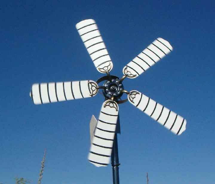
In the meantime my ceiling fan conversion will continue to spin on the 10 ft pole testing its ability to not fly apart not doing any work. I have already made some modifications beefing up and installing a air brake to keep it together. The air brake can be seen in the picture below.


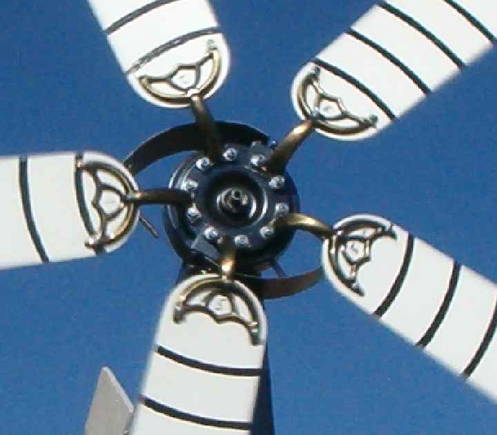
Also in this next picture can be seen the spiral I have painted on the blades to estimate the rpm.

It takes 8 turns for the spiral line to go from the tip of a blade to the center.  So I just count the number of spirals per minute and multiply by 8 and I have the rpm.


Probably this next question should have been put on a new thread but hope this is ok to ask it here. This induction motor is shown below.  If instead of turning down the rotor, replace it with the shaft shown beside it and turning down the other end to fit the bearing, would this steel shaft be suitable for cementing and incasing in epoxy?  Or must it be made of a non magnetic material such as aluminum like the original rotor?


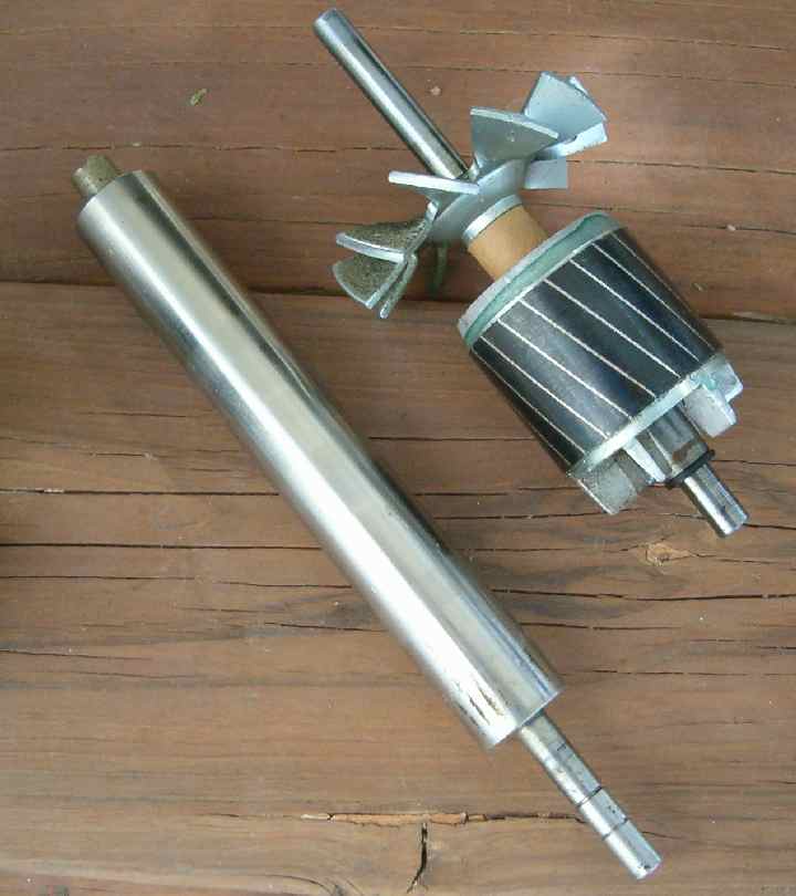
It just happens that this other shaft is the same size as the orig. rotor would be if all the segments were machined off.  Also the turned down end is the same size as the motor bearing shaft.


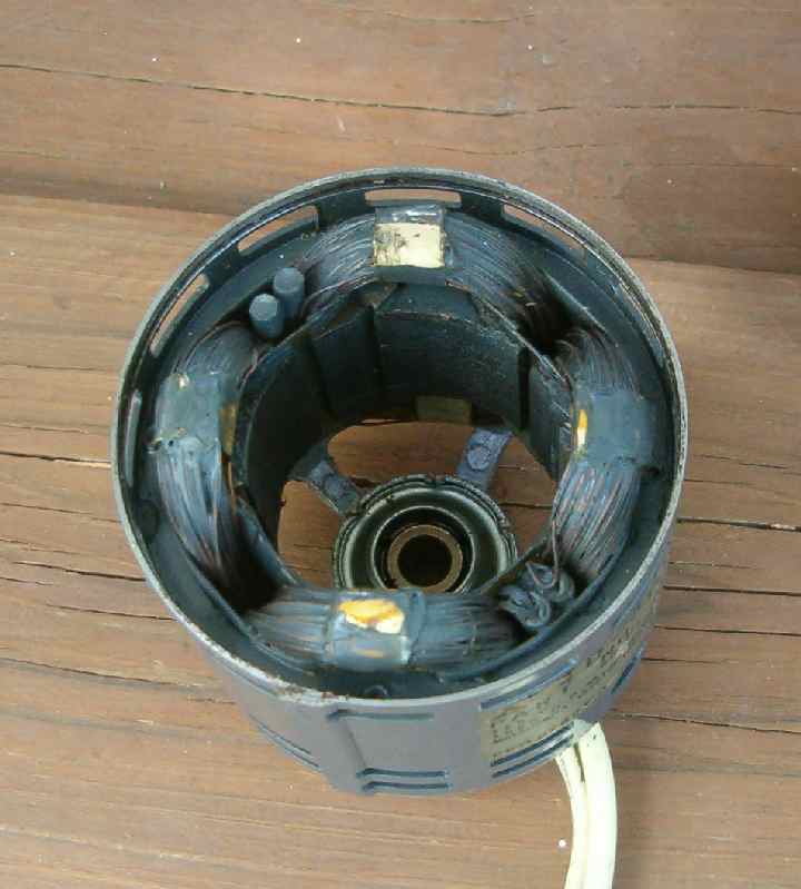
This picture is the 4 pole stator:


Thank you all for being so helpful.

AT


P.S. Just as I was finishing this reply up my neighbor brought my fan windmill over to me in peaces.  The nut on the short threaded mounting end of the motor worked loose and it fell to the ground and broke all the fan mounts.  Looks like I will be looking for another ceiling fan. "Bummer"

« Last Edit: June 05, 2007, 07:57:43 PM by allthumbs »

stephent

  • Sr. Member
  • ****
  • Posts: 268
Re: Ceiling fan wind generator
« Reply #22 on: June 05, 2007, 09:27:31 PM »
That other shaft should work, more then likely, turned down for the bearings.

Using  steel "under" the mags is ok, maybe even helpful. Steel close beside or between mags isn't, especially about the same height as the mags are.

New motor looks like a only "fair" one to start with,  do note --sleeve/oilite bearings won't hold up as well as ball bearings. Also might want to look for a thermal cutout just across from the wire legs going out. Look at the name tag for "thermally protected" somewhere--if so, it has one, and maybe even if not labeled. But easily removed. (they usually look like a small squarish can with 2 wires out)

It's going to be hard to get decogged with 4 windings and short, wide  laminations also, without using mags skewed just right. Probably going to be a bear actually.

A 1/4th or 1/3rd (or bigger) hp, ball bearing type motor (even a single phase with start/run windings) with many more (narrower) lamination "teeth" would make a first try much easier for decogging.

Dinges posted a good decogging article on this forum.

« Last Edit: June 05, 2007, 09:27:31 PM by stephent »

ghurd

  • Super Hero Member Plus
  • *******
  • Posts: 8059
Re: Ceiling fan wind generator
« Reply #23 on: June 06, 2007, 08:09:09 AM »
I think it will be easier to use the factory rotor.


The magnets need iron under them (or behind them in the ceiling fan).

The distance from the magnets to the lamintions (the 4 'teeth') needs to be as small as possible.  Magnets are 'expensive', so building up the new rotor with magnets will cost something.  And too much magnet may cause problems other than more cogging.


Me? I would put a handfull of small (cheap neo) magnets on each pole, in a skewed patern to reduce the cogging, and see what it does.  It'll work. You will learn a lot.  And it won't take a lot of time or money.


This one works quite well... Honest!

http://www.otherpower.com/images/scimages/2050/3phHD.jpg


Everybody starts somewhere.  It would be a good start.

G-

« Last Edit: June 06, 2007, 08:09:09 AM by ghurd »
www.ghurd.info<<<-----Information on my Controller

allthumbs

  • Newbie
  • *
  • Posts: 23
Re: Ceiling fan wind generator
« Reply #24 on: June 06, 2007, 04:45:30 PM »


The last motor had only 4 poles this one has 34 poles.


I notice that sPuDd and his washing machine conversion had 36 poles and he used 8 rows of magnets.


  1. Would 8 rows work for this one?
  2.  If I turn down the rotor as sPuDd did would you recommend the 13mm x 5mm disk neos stacked as he did or would there be a better less expensive choice?


I could also make a rotor on my lathe with a 1" diameter and then would need 1" or stacked ½" neos.


3. Would 10% skew be about right?  I notice that sPuDd and his washing machine

conversion did not place the skewed rows of magnets evenly around the rotor but put 2 rows and then a wider space.  I believe he called it 3x2 configuration. What does that mean?  Does it mean that they are 3" & 2" apart?


  1.  Does the centrifical switch shown above actuate some start windings and would they be any value for the gen?
  2.  I did not understand if he had to cut and extend any wires to get the 2 phase or can the stator coils be used as they are or will I need to cut into them somewhere for maybe 2 phase?  Please illustrate! It will be hard to find where the coils begin and end.


I know then that I will need 2 bridge rectifiers and whatever else. Will cross that bridge when I come to it.

AT
« Last Edit: June 06, 2007, 04:45:30 PM by allthumbs »

stephent

  • Sr. Member
  • ****
  • Posts: 268
Re: Ceiling fan wind generator
« Reply #25 on: June 06, 2007, 09:47:45 PM »
Last motor is a 4 pole (1725 rpm).

Use 4 "poles" of mags on armature of maybe 1/4" or 3/8" thickness (I doubt if any more depth would be of use in this smaller motor size)

Take out the starting winding cutout stuff and use the start winding coils too.

More then likely you will be able to rectify the main windings and start windings separately and then join at the batt.

Use the windings as is...no rewinding or cutting except for getting the start winding separated from the cutout contacts and getting it out.


Looks like a total of 1 1/2 or max of 2 cubic inches of mags should work...

Make mag pole width about center of winding "hole" size or maybe a tad wider/narrower (little secret--a mags major "force" isn't as wide as the mag really--test is stick a screwdriver to edge of mag pole face and see how it likes it, a little wider doesn't hurt as bad as narrower)

/me waits for arguments here.


--skew the mags about the same as original lamination angle

Still looks like sleeve bearings tho....still workable, but won't last as long.

Prop size?--ask zubbly, he's been close on a lot.

Make it furling type mount.

« Last Edit: June 06, 2007, 09:47:45 PM by stephent »

dinges

  • Hero Member
  • *****
  • Posts: 1294
  • Country: nl
Re: Ceiling fan wind generator
« Reply #26 on: June 06, 2007, 10:26:47 PM »
It's hard to reply without knowing more about your motor, but I've done a small conversion as well. A few pix can be found here:


http://www.anotherpower.com/gallery/album48

http://www.anotherpower.com/gallery/dinges/mini_induction_conv_nr_2

http://www.anotherpower.com/gallery/dinges/mini_induction_conv_nr_2_rotor_and_original_motor

http://www.anotherpower.com/gallery/dinges/mini_induction_conv_nr_2_rotor_WIP

http://www.anotherpower.com/gallery/dinges/mini_induction_rotor_marked

http://www.anotherpower.com/gallery/dinges/mini_induction_conversion_nr_2


I loctited a new steel rotor core on the original shaft. The pictures should make it clear.


You must take measures to prevent cogging. For more on decogging, I suggest you read this:


http://www.otherpower.com/images/scimages/3538/decogging_tutorial_V1.pdf


Plus, read the 3 pdf files that Zubbly wrote on motorconversions.


It's not rocket science, but by reading and learning you can prevent frustrating mistakes.


Succes,

« Last Edit: June 06, 2007, 10:26:47 PM by dinges »
“Research is what I'm doing when I don't know what I'm doing.” (W. von Braun)

ghurd

  • Super Hero Member Plus
  • *******
  • Posts: 8059
Re: Ceiling fan wind generator
« Reply #27 on: June 07, 2007, 07:47:07 AM »
arguments- With more teeth, cogging will (often) be a lot less troublesome.

Does that count?


The 3x2 is 3 magnets high by 2 magnets wide.


The last motor has 4 poles, and 34 teeth or slots.

I believe it is the easiest one shown to convert.

I wouldn't worry about the bearings, because most people will move on to "something better" after the first one.

G-

« Last Edit: June 07, 2007, 07:47:07 AM by ghurd »
www.ghurd.info<<<-----Information on my Controller

allthumbs

  • Newbie
  • *
  • Posts: 23
Re: Ceiling fan wind generator
« Reply #28 on: June 07, 2007, 08:53:51 PM »
Could someone show a picture of a furling type mount? Also how it works?


Buy the way the bearings are ball bearings, My pic just didn't show enough to identify them.

AT

« Last Edit: June 07, 2007, 08:53:51 PM by allthumbs »

TomW

  • Super Hero Member Plus
  • *******
  • Posts: 5130
  • Country: us
Furling Drawing
« Reply #29 on: June 07, 2007, 09:42:21 PM »
Thumbs;


Found this over in Danb's file area:


He has more stuff there but this is the "current" method many use.


Cheers.


TomW

« Last Edit: June 07, 2007, 09:42:21 PM by TomW »

allthumbs

  • Newbie
  • *
  • Posts: 23
Re: Furling Drawing
« Reply #30 on: June 10, 2007, 10:52:50 PM »
Yes TomW I went to DanB's file area and the "other stuff" there explained quite well the things that I did not understand.  Thanks Tom.

AT
« Last Edit: June 10, 2007, 10:52:50 PM by allthumbs »

Jeff

  • Full Member
  • ***
  • Posts: 153
Re: Ceiling fan wind generator
« Reply #31 on: July 11, 2008, 01:12:39 PM »
WOW! I got lucky & found this topic "searching" the board. This is the same exact configuration of a cieling fan I have. I have been researching this 3-4 days now on this board, and have a Word document about 12 pages long so far.

I hate to stick my head in the lion's mouth, but for me, most people(s) solutions for this are either too greedy for the amount of power, or too expensive for my budget. Sorry everyone, I have no income, and 1-2 amps extra charging power into my battery bank would mean the world to me.

I've so far learned not to even think of using the blades that come on a cieling fan. I have collected parts to make a larger (55 gal. drum size) VAWT to power this with.

Please feel free anyone, to contact me further about this.
« Last Edit: July 11, 2008, 01:12:39 PM by Jeff »

16kw

  • Newbie
  • *
  • Posts: 1
Re: Ceiling fan wind generator
« Reply #32 on: February 03, 2009, 01:08:33 PM »
HELLO, I HAVE JUST MADE A CEILING FAN GENERATOR, WHEN I SPIN IT BY HAND I GET 15 VOLTS. I REPLACED THE OUTER RING WITH AN ALLY ONE AND PUT IN 20 5MM ROUND NEOS. I CAST THE RING THEN TURNED IT UP ON MY LATHE.IN THE FIRST RING I PUT THE MAGNETS AT RIGHT ANGLES TO THE COILS AND GOT 1.5 VOLTS. I CAST NUMBER 2 AND DRILLED IT AND PUT THE MAGNETS THE SAME AS YOUR PICTURE, I GET VERY LITTLE COGING AND 15 VOLTS JUST SPINING IT BY HAND, IF ANYBODY WANTS ANY PICS I WILL TRY TO PUT THEM ON THE FORUM   KEITH
« Last Edit: February 03, 2009, 01:08:33 PM by 16kw »