Author Topic: Floppy Stepper motor Windmill  (Read 11917 times)

0 Members and 1 Guest are viewing this topic.

prabs

  • Newbie
  • *
  • Posts: 6
Floppy Stepper motor Windmill
« on: October 31, 2006, 07:27:41 AM »
I have just bought a old Floppy drive(5 ¼") Stepper motor to build a Windmill. It has 5 wires.  Made a quick propeller and it spins nicely and when checked with the Multimeter it shows 4 to 6 V AC.

 Is it possible to combine the outputs of 2 or 3 Windmills to charge a 12V Battery.

 Has anyone experience with using this motor to build a Windmill. I will be thankful if could please let me know of your experience. Thanks.

 
« Last Edit: October 31, 2006, 07:27:41 AM by (unknown) »

claude

  • Full Member
  • ***
  • Posts: 129
Re: Floppy Stepper motor Windmill - are you sure?
« Reply #1 on: October 31, 2006, 02:34:38 AM »
Hello prabs,


I'm pretty much into steppers lately. I've been working on a windmill that's using the same floppy drive motor but I ended replacing it with a inkjet one. Check out this story, it may shed some light: http://www.fieldlines.com/story/2006/10/10/212737/59


The floppy stepper originally installed worked great but when I took it for a test drive outside my car's window, the results were shocking and dissapointing too. At 20 km/h the 50 cm diameter propeller (plastic pipe) started to spis beyond visible and the sound became frightening so I kept the test below that speed.


The voltage was 80+ Volts (I used a 100V capacitor to smooth out the voltage after the rectifiers) and I said wow, that's fantastic. It seemed to easily top that should the car went faster. But when checking the miliamps I was dissapointed. The best output (it quickly became fixed at 15 km/h, no speed change would improve that) was 0.05A. How's that for a windmill? One LED would be happy to live with that but that's about it.


I took that stepper out and put another one from a inkjet printer. It had a bit of cogging but the output was much more usable. 6-11 Volts at 0.25 mAmps.

I don't know how two of these could be put connected so as to sum up the output. If anybody knows, i'm interested too. I anticipate problems though.


Claude

« Last Edit: October 31, 2006, 02:34:38 AM by claude »

claude

  • Full Member
  • ***
  • Posts: 129
Re: Floppy Stepper motor Windmill - are you sure?
« Reply #2 on: October 31, 2006, 02:47:11 AM »
I found this - it may give you the answer. But I know as much as you do in this area. It seems you could sum up the AC output from the steppers and place both of them on the same rectifier. The differences in phase need to be smoothed with a capacitor. I usually use 47uF/100V electrolitic ones.

http://www.fieldlines.com/story/2006/10/27/72319/355

« Last Edit: October 31, 2006, 02:47:11 AM by claude »

Opera House

  • Sr. Member
  • ****
  • Posts: 261
Re: Floppy Stepper motor Windmill
« Reply #3 on: October 31, 2006, 03:38:37 AM »
With a 5 wire stepper motor you are best off using a cap input voltage doubler on the four windings to the center lead.
« Last Edit: October 31, 2006, 03:38:37 AM by Opera House »

tecker

  • SuperHero Member
  • ******
  • Posts: 2183
Re: Floppy Stepper motor Windmill
« Reply #4 on: October 31, 2006, 03:48:05 AM »
Look at the voltage from the coils and see if you can't star them at the motor and then rectify .
« Last Edit: October 31, 2006, 03:48:05 AM by tecker »

Norm

  • Hero Member
  • *****
  • Posts: 1841
  • Country: us
  • Ohio's sharpest corner
Re: Floppy Stepper motor Windmill
« Reply #5 on: October 31, 2006, 06:31:17 AM »
 It's so much easier to charge a small 6 volt battery with a good stepper motor....easier yet to charge a couple of rechargable AA batteries....

then just put 10 cells in series for 12 volts.


.....5 windmills each charging 2 AAs..


        ( :>) Norm.    

« Last Edit: October 31, 2006, 06:31:17 AM by Norm »

ghurd

  • Super Hero Member Plus
  • *******
  • Posts: 8059
Re: Floppy Stepper motor Windmill - are you sure?
« Reply #6 on: October 31, 2006, 07:01:38 AM »
The 5th wire causes problems. The linked circuit will not work with a 5 wire motor.

My best luck has been a single diode on each of the 4 outputs, to positive. Then the common 5th wire to negative.  The voltage is still to low.


I would try another stepper with higher voltage. 4, 6, or 8 wires have been best for me.

G-

« Last Edit: October 31, 2006, 07:01:38 AM by ghurd »
www.ghurd.info<<<-----Information on my Controller

veewee77

  • Full Member
  • ***
  • Posts: 244
Re: Floppy Stepper motor Windmill - are you sure?
« Reply #7 on: October 31, 2006, 11:04:30 AM »
It is possible to put several stepper mills together to make 12V, however, each one would need to be run through it's own rectifier and then charge a cap and then series the caps to make 12V.  Meaning a lot of extra wire between the mills inless they are all very lose together.


Stepper mills are pretty much "toys" and good demo units but for serious power (even a radio would be serious in this case) you need more than that.


Doug

« Last Edit: October 31, 2006, 11:04:30 AM by veewee77 »

nothing to lose

  • Hero Member
  • *****
  • Posts: 1538
Re: Floppy Stepper motor Windmill
« Reply #8 on: October 31, 2006, 12:27:01 PM »
You may have an idea there perhaps.

Look at all the things that use AAA, AA, C , D, batteries. Recharge them from steppers or such at 1.5V and avoid the losses with those pesky 120V rechargers.


Hmmm, I got broke printers and other steppers, kid has portable CD player eating AA's, hide her charger and give her a couple steppers, I bet she'll build her own wind genny then :)

« Last Edit: October 31, 2006, 12:27:01 PM by nothing to lose »

RogerAS

  • Sr. Member
  • ****
  • Posts: 329
Re: Floppy Stepper motor Windmill
« Reply #9 on: October 31, 2006, 01:18:56 PM »
Hi Prabs,


I don't know what's going on with your stepper, but mine produce way more voltage and current than your posted numbers. With no load and a steady breeze mine will go well over 25V DC. I get around .5 amp from each one into my 12V bank. I use a couple different rectification methods, but both have a pretty high value cap on the DC side of the rectifiers. Some have bridges and some have single diode arrays. Somewhere around 5000uf 35V for the caps. Mine will blow LED's to bits when hooked up to the output without resistors! I've done that just for fun. I do not series the DC output from bridges. I use a 20" box fan blade as the mill's blade. I've used the 5 blade and 3 blade version with almost equal results. These blades tend to stall at a point where the steppers output will go no higher. I have 8 of these flying and they do add up. I've seen over 5 amps into my bank from these. 2 of these are into their third winter of operation.


Are these the read/write head position steppers? I think you're seeing 4 - 6V per phase on the AC side. With 2 AC phases and an extra wire you should be seeing well over 15V when spun with your fingers after recification.


There are some old 5.25" drives that have a pancake motor to spin the disc. These also make good small turbines with much higher output, but there is a problem with them. Most do not have a good bearing set and they are enabled by ceramic magnets. However with a little work a small dual rotor can be made from the coils and 12 neo mags. I have one I made, not currently flying, that could hit 4 + amps.


The following is a simple ASCII drawing of the single diode arrays for the 5 wire type stepper. If you find a stepper with more phases just add more diodes. The period between the >(diode symbol) is a connection point for the stepper output AC wires. Just make sure the band on one end is facing the same way for all the diodes, and the banded end should be positive DC. Before sending that DC to the battery bank I insert a capacitor { this symbol | ) }, with another diode blocking the bank from charging that cap(s) with no wind. Actually I have that last blocking diode just before all the combined steppers output goes into the bank.


_> . > +

_> . > +

_> . > +

_> . > +

_> . > +

_   | )  +

      >+


Keep trying! To some these may be toy turbines, but I get useful power from mine and I think you can to if you work at it a little. 5 amps may not sound impressive until one considers I have around $2 - $3 in each turbine!


Hope this helps,

« Last Edit: October 31, 2006, 01:18:56 PM by RogerAS »

richhagen

  • Hero Member
  • *****
  • Posts: 1597
  • Country: us
Floppy Stepper motor Windmill
« Reply #10 on: October 31, 2006, 03:47:10 PM »
You would need to ensure that youre loads were disconnected with the first cell to reach its maximum operational depth of discharge, otherwise you would risk damaging a cell if some turbines charged better than others.  If you had some type of balancing circuit to equalize the charge of the cells, that should work as well.  Rich
« Last Edit: October 31, 2006, 03:47:10 PM by richhagen »
A Joule saved is a Joule made!

tecker

  • SuperHero Member
  • ******
  • Posts: 2183
Re: Floppy Stepper motor Windmill
« Reply #11 on: November 01, 2006, 04:06:23 AM »
Here's a mod you can do to most computer fans to get them to charge modestly you can through hole the magnet hub for blades.(Got to watch your balance though the shaft is small but the blades ca be very light ) I stick some light blade on one and check it out .  I put some neos on this unit for grins and use it under the hood of my car to get an idea how much air is going through the area under the hood in different places . basically you loop a wire under the posts of too coils there is usually four coils the inside loop stared you might need to cut the comutator diodes . I put a pic of a 4.5"  apart for those who want to tackle it. this one takes a 1/8 inch snap ring over the shaft end .The neos in place you have to give it a bump from the " power in " to get it to turn with stock blades but it pumps out 250 t0 500  mill at 18 to 25 volts at 35 miles an hour ,(stock blades) with the stock mags around 15 to 20 volts but the amps are low (the sine wave looks nice very uniform) .


http://www.otherpower.com/images/scimages/1431/fan_adaption.jpg


 http://www.otherpower.com/images/scimages/1431/fan_adaption_002.jpg

« Last Edit: November 01, 2006, 04:06:23 AM by tecker »

tecker

  • SuperHero Member
  • ******
  • Posts: 2183
Re: Floppy Stepper motor Windmill
« Reply #12 on: November 01, 2006, 04:08:24 AM »
Spelling override sorry
« Last Edit: November 01, 2006, 04:08:24 AM by tecker »

prabs

  • Newbie
  • *
  • Posts: 6
Re: Floppy Stepper motor Windmill
« Reply #13 on: November 01, 2006, 04:55:15 AM »
Hi Roger

  Thanks for everyone who have posted their responses.  I am using a read/write head position stepper motor from old Floppy drive(5 ¼") . I cannot verify the output with a 3V Bulb, looks like it simply shorts and the motor vibrates reducing the speed. The voltage exceeds 10V AC on the multimeter for a strong wind.

 A few questions i would like to ask you.


  1. Whats your battery bank(I am new to this and need to explore a lot!!!) configuration.
  2. How do you sum up the output. Do you use 2 full wave bridge rectifiers for each Windmill. Whats the resistance value in each circuit.
  3. Is 5000uf 35V capacitor it suitable for charging the battery bank.
  4. What is the blade diameter. I am using 35 cms as diam.


prabs
« Last Edit: November 01, 2006, 04:55:15 AM by prabs »

ghurd

  • Super Hero Member Plus
  • *******
  • Posts: 8059
Re: Floppy Stepper motor Windmill
« Reply #14 on: November 01, 2006, 07:00:12 AM »
Hi Roger!


You know I can't resist getting in on this.  

I think I tried it with less than good results, but I don't think I used the 5th wire.


You always connect the 5th wire the same as the other 4?


Does the cap help?  Enough to make up for the extra diode drop?

Is the cap on the windmill instead of near the battery?


This is what you mean, right?

G-


« Last Edit: November 01, 2006, 07:00:12 AM by ghurd »
www.ghurd.info<<<-----Information on my Controller

prabs

  • Newbie
  • *
  • Posts: 6
Re: Floppy Stepper motor Windmill
« Reply #15 on: November 01, 2006, 08:08:02 AM »
Thanks Ghurd. Nice circuit diagram. And how about a second stepper motor output added to this. Please explain me.

"Just make sure the band on one end is facing the same way for all the diodes, and the banded end should be positive DC."

All the diodes - diodes of all the Mills or all the diodes of one mill?


Lets confirm with Roger.


prabs

« Last Edit: November 01, 2006, 08:08:02 AM by prabs »

prabs

  • Newbie
  • *
  • Posts: 6
Re: Floppy Stepper motor Windmill
« Reply #16 on: November 01, 2006, 08:12:49 AM »
Roger

 You have mentioned 8 Windmills add up to charge your battery bank. How many you need at the minimum to charge a battery bank of 12 volts.

prabs
« Last Edit: November 01, 2006, 08:12:49 AM by prabs »

ghurd

  • Super Hero Member Plus
  • *******
  • Posts: 8059
Re: Floppy Stepper motor Windmill
« Reply #17 on: November 01, 2006, 08:38:17 AM »
If the diagram is what Roger explained,

All the windmills will be seperate and wired like in the diagram,

but all windmills connected to one battery.


Most steppers will make 12V after proper wiring.

Enough voltage is not often a problem. Low amps is usually the problem.


Roger?

« Last Edit: November 01, 2006, 08:38:17 AM by ghurd »
www.ghurd.info<<<-----Information on my Controller

RogerAS

  • Sr. Member
  • ****
  • Posts: 329
Re: Floppy Stepper motor Windmill
« Reply #18 on: November 01, 2006, 03:03:18 PM »
Prabs & Ghurd,


The drawing is correct for the diode array. To use that 5th wire with bridges just add another bridge. The caps just smooth things out, unless I'm running my pulser circuit as seen below, at which point they become tiny little batteries. The caps main function, without the pulser circuit, is to smooth out the DC. Since these little motors don't have a voltage issue the final diode drop is not too worrisome for me. Yes each mill is treated individually, then the combined output fed to the bank. I don't think my 8 stepper mills would keep my 1320 AH 12V bank charged (14 6V 220AH golf carts). The wind would have to be in the +20 MPH range for some time. The blades are from dead 20" box fans. If I had 30 of these things it MIGHT keep up with the drain on my bank if I was in a really good wind zone, alas we get good wind only in the winter, aside from thunderstorms. I don't rely on these alone as we have 750+watts of solar and I have a Kubota diesel driving a large frame automotive alternator. I also have 2 GE ECM motors up and running as mills as well.


I think the resistance for each phase is 17 Ohms, on the TEAC motors. I have other makes so I can't say for sure as they're up and covered! I've replaced the bushings with sealed bearings on a couple of the "can" type steppers from inkjet printers that had much lower phase resistance. If it weren't such a hassel to replace the bushings I would replace all the drive steppers with that type.


My 8 steppers might be able to charge a single 12V battery given enough time and wind. I just see it like this. 12V X 5A=60watts. I have $2-$3 invested in each. That works out to about $.25 per watt, which is way cheap. I didn't pay for even the 5.25" drives, as they are throw away "junk" computer equipment. The caps and diodes/bridges are also salvaged items from other tossed electronics. The JB weld, solder and other bits are all I had to buy. Prabs, check out all the computer shops in your area to see what's out there. Ask schools for old equipment.


The schematic below is a good way to use the low amperage output of these or other steppers. The first NE555 acts as a multivibrator, setting the pulse frequency via C1 and the 250K variable resistor. The second NE555 acts as a one shot, setting the duration of the pulse via C2 and the 100K variable resistor. The LM7805 limits the voltage to the timers and protects them from the voltage swings common to wind power. The FET drives the negative side pulses into the battery bank. The 18V zenner diode protects the whole show by turning on the FET if the voltage goes too high between pulses, and dumping the capacitors on the mills power without the drive from the timers. With a good wind and this circuit running I have seen both elements of an 1157 bulb flash very brightly. One could build a very large capacitor bank right at the circuit, just ahead of the LM7805, and get some pretty stiff pulses by lengthening the fequency accordingly. No, one does not gain power using this, but rather let the steppers spool up free of the clamping action of being directly connected to the battery bank. This allows the voltage to build in the capacitors and then suddenly drain them. Whether this pulsng action helps battery desulphation or not is open to debate, but I like seeing the needle jump on my analog voltmeter when it fires. One could run this directly from the battery bank, eleminate the 18V zenner and LM7805, and adjust the frequency to make a crude desulphator.
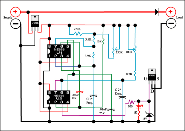


Hope this helps,

« Last Edit: November 01, 2006, 03:03:18 PM by RogerAS »

Norm

  • Hero Member
  • *****
  • Posts: 1841
  • Country: us
  • Ohio's sharpest corner
Re: Floppy Stepper motor Windmill
« Reply #19 on: November 01, 2006, 03:07:45 PM »
  Good afternoon Ghurd....

  Well Hey I've got red,orange,yellow,brown and

black wires (electronically challenged )on those

RT stepper motors ( LOL) but I think it might

work anyway....what value would I need on the

cap ?

             ( :>) Norm
« Last Edit: November 01, 2006, 03:07:45 PM by Norm »

nothing to lose

  • Hero Member
  • *****
  • Posts: 1538
Re: Floppy Stepper motor Windmill
« Reply #20 on: November 02, 2006, 12:54:58 AM »
I am thinking just a couple cells in a battery holder per genny for recharging them.

Like wire the holder permanant and change batteries as needed for recharging.


Some steppers and 12" blades might work nice for charging some BruceS cells also.

« Last Edit: November 02, 2006, 12:54:58 AM by nothing to lose »

claude

  • Full Member
  • ***
  • Posts: 129
Re: Floppy Stepper motor Windmill
« Reply #21 on: November 02, 2006, 04:40:50 AM »
Hello RogerAS,


Great pulser circuit. What is the minimum input and how it affects frequency or duration? And what about the pulses? Have you measured its peak voltage and amperage?


Also, I see that C1 and C2 are left to user choice. What are your reccomendations?


What about "One could build a very large capacitor bank right at the circuit, just ahead of the LM7805" - how large? I have several large capacitors salvaged from various power supplies. They are high voltage and the uF values are not similar.


I'm really interested in this as I have a lot of steppers and plans to use them.

« Last Edit: November 02, 2006, 04:40:50 AM by claude »

ghurd

  • Super Hero Member Plus
  • *******
  • Posts: 8059
Re: Floppy Stepper motor Windmill
« Reply #22 on: November 02, 2006, 08:51:41 AM »
With the RT steppers and what you are doing,

I don't think I'd bother with the cap and last single diode.

I'll try it both ways and let you know in a few days.

The colors don't matter for this circuit.


NTL is right,it looks like it will charge a 19.2V pack.

NTL has a 'Rubber Tire Stepper' too, with a red LED stuck in it.

G-

« Last Edit: November 02, 2006, 08:51:41 AM by ghurd »
www.ghurd.info<<<-----Information on my Controller

RogerAS

  • Sr. Member
  • ****
  • Posts: 329
Pulser ?'s
« Reply #23 on: November 02, 2006, 04:02:34 PM »
Claude,


Well the minimum input voltage wise must be >5V to make the 555's function, but that won't help unless one is pulsing <5V batteries. There is no voltage gain with this design. Whenever the supply voltage rises above the battery voltage the pulses act to charge the bank. Since I use the LM7805 to limit the voltage (5V positive)  to the 555's the elevated supply voltage has little to no effect on pulse duration or frequency. This regulator protects the 555's from the flucuations common to wind power. As for the values of C1 & C2 one needs to experiment some. The greater the supply's power the faster one needs to run the frequency, and the higher available amperage the longer the duration of these pulses. Care should be taken to not make the frquency too fast for the pulse duration or it will never time out. In other words don't allow an overlap or it will either always be "on" or it will never be "on", or it will stutter (miss beats or pulses). I'd start with a 1000uF for C1 and maybe a 200uF for C2. Since the use of 25V caps is overkill in a 5V circuit they should last well past their life expectancy. C1 will increase frequency as its uF rating drops, as will the pulse width for C2.


As long as the bank of capacitors are higher voltage rated than they are ever likely to "see" it really doesn't matter if they are mixed values. Just wire all the positive sides together and all the negative together, and NOT in series. Making the wiring good an beefy from the caps to the battery bank will help transfer the power better.


Using this basic design one could build a basic square wave inverter. With a frequency measuring device set the pulses to 60 or 50 cycles per second from 555#1. From the output pin on 555#2  (pin 3) install a small driving transitor, I think an NPN 2222 would work. Use that transitors ouput to in turn drive a high value FET or bank array of them. The negative pulses from the FET(s) are then fed to one step up transformer leg, and the other transformer leg is always hooked to the positve rail. The output of the transformers amperage is controlled by the pulse width. In such a circuit the zenner or LED is not needed, and if driven from a 12V supply the LM7805 isn't needed. A 10-1 steup transformer would supply 120V square wave AC. If one were to add several "slave" 555's and associated FET's a modified square wave could be produced. Say the first "slave" turns on for 1/60th of a second, the second a shade less and so on and so on the transformer would saturate in steps relative to the added inputs of the "slaves". Be aware that the transformer will run hot using this idea. I haven't actually tried this so it is all vaporware but it should work.


Take care all,

« Last Edit: November 02, 2006, 04:02:34 PM by RogerAS »

richhagen

  • Hero Member
  • *****
  • Posts: 1597
  • Country: us
Re: Floppy Stepper motor Windmill
« Reply #24 on: November 02, 2006, 06:01:03 PM »
If you are only charging them then that would work fine, but if you had a setup where you were charging 6 strings of 2V independently and drawing them down together at 12V, I think you would have a problem keeping the cells equalized.  Rich
« Last Edit: November 02, 2006, 06:01:03 PM by richhagen »
A Joule saved is a Joule made!

nothing to lose

  • Hero Member
  • *****
  • Posts: 1538
Re: Floppy Stepper motor Windmill
« Reply #25 on: November 02, 2006, 07:54:26 PM »
Thanks Rich.


Hows the 12" blades and stepper with the super caps doing? Kinda what I have in mind for these AA rechargables and BruceS batteries. I am using portable battery operated things at time here now. I think 4 setups likes yours going into 4 banks of batteries just for charging should work well for me. Keep the wall charger put away for awhile.

« Last Edit: November 02, 2006, 07:54:26 PM by nothing to lose »

richhagen

  • Hero Member
  • *****
  • Posts: 1597
  • Country: us
Re: Floppy Stepper motor Windmill
« Reply #26 on: November 03, 2006, 04:38:21 PM »
It is still up and working fine, right where you last saw it.  Except on really calm days, it keeps a couple LED's lit to add to the light there.  Rich
« Last Edit: November 03, 2006, 04:38:21 PM by richhagen »
A Joule saved is a Joule made!